БЛОК ЦИЛИНДРОВ ПРОВЕРКА

PROCEDURE
-
CLEAN CYLINDER BLOCK SUB-ASSEMBLY
-
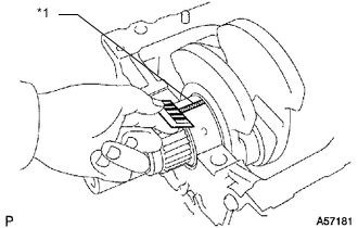
Using a gasket scraper, remove all the gasket material from the top surface of the cylinder block.
-
Using a soft brush and solvent, thoroughly clean the cylinder block.
-
-
INSPECT CYLINDER BLOCK SUB-ASSEMBLY
-
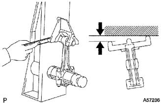
Inspect for flatness.
-
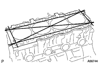
Using a precision straightedge and feeler gauge, measure the surfaces that contacts the cylinder head and main bearing cap for warpage.
Maximum warpage 0.20 mm (0.00787 in.) If the warpage is more than the maximum, replace the cylinder block.
-
-
Visually check the cylinder for vertical scratches. If deep scratches are present, rebore all 4 cylinders. If necessary, replace the cylinder block.
-
-
INSPECT CYLINDER BORE
-
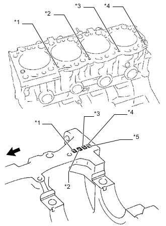
Text in Illustration *1 No. 1 *2 No. 2 *3 No. 3 *4 No. 4 *5 Mark 1, 2 or 3 
Front Inspect the cylinder bore diameter.
Tech Tips
There are 3 sizes of the standard cylinder bore diameter, marked "1", "2" and "3" accordingly. The mark is stamped on the lower left rear of the cylinder block.
-
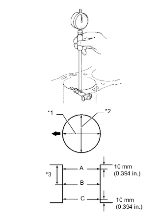
Text in Illustration *1 Axial Direction *2 Thrust Direction *3 Center Front Using a cylinder gauge, measure the cylinder bore diameter at positions A, B and C in the thrust and axial directions.
Standard Diameter Item Specified Condition Mark 1 99.500 to 99.510 mm (3.9173 to 3.9177 in.) Mark 2 99.510 to 99.520 mm (3.9177 to 3.9181 in.) Mark 3 99.520 to 99.530 mm (3.9181 to 3.9185 in.) Maximum Diameter Item Specified Condition STD 99.73 mm (3.93 in.) O/S 0.50 100.23 mm (3.95 in.) If the diameter is more than the maximum, rebore all cylinders. If necessary, replace the cylinder block.
-
-
-
CLEAN PISTON SUB-ASSEMBLY WITH PIN
-
Using a gasket scraper, remove the carbon from the piston top.
-
Using a groove cleaning tool or broken ring, clean the piston ring grooves.
-
Using solvent and a brush, thoroughly clean the piston.
Note
Do not use a wire brush.
-
-
INSPECT PISTON SUB-ASSEMBLY
Tech Tips
There are 3 sizes of standard piston diameter, marked "1", "2" and "3" accordingly. The mark is stamped on the piston top.
-
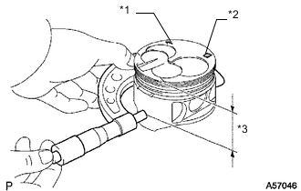
Text in Illustration *1 Front Mark *2 Size Mark *3 Distance Using a micrometer, measure the piston diameter at right angles to the piston center line where the distance from the piston head is as specified.
Distance 61.27 to 61.33 mm (2.41 to 2.42 in.) Standard Piston Diameter Item Specified Condition Mark 1 99.450 to 99.460 mm (3.9153 to 3.9157 in.) Mark 2 99.460 to 99.470 mm (3.9157 to 3.9161 in.) Mark 3 99.470 to 99.480 mm (3.9161 to 3.9165 in.) O/S 0.50 99.950 to 99.980 mm (3.935 to 3.936 in.)
-
Measure the cylinder bore diameter in the thrust directions.
-
-
-
INSPECT PISTON OIL CLEARANCE
-
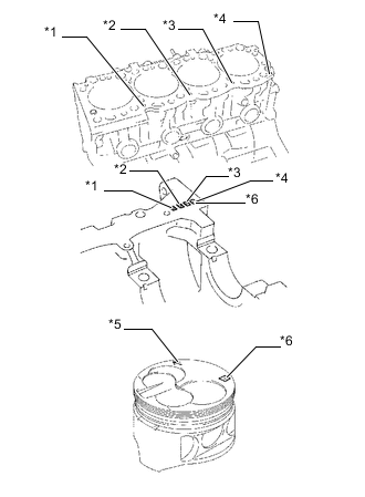
Text in Illustration *1 No. 1 *2 No. 2 *3 No. 3 *4 No. 4 *5 Front Mark *6 Mark 1, 2 or 3 Subtract the piston diameter measurement from the cylinder bore diameter measurement.
Standard oil clearance 0.040 to 0.060 mm (0.00157 to 0.00236 in.) Maximum oil clearance 0.13 mm (0.00512 in.) If the oil clearance is more than the maximum, replace all 4 pistons and rebore all 4 cylinders. If necessary, replace the cylinder block.
Tech Tips
Use a piston with the same number mark as the cylinder diameter marked on the cylinder block.
-
-
INSPECT PISTON PIN OIL CLEARANCE
Tech Tips
When replacing the piston sub-assembly (w/ pin) with a supply part, there are a number of piston diameter sizes to choose from, but there is only one size of piston pin diameter.
-
Inspect the piston pin fit.
-
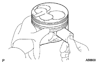
Heat the piston to approximately. 60°C (140°F), and push the piston pin into the piston pin hole with your thumb.
If the pin can be installed at a lower temperature, replace the piston and pin as a set.
-
-
Using a micrometer, measure the piston pin diameter.
Standard piston pin diameter Item Specified Condition Mark A 29.000 to 29.004 mm (1.1417 to 1.1419 in.) Mark B 29.004 to 29.008 mm (1.1419 to 1.1420 in.) Mark C 29.008 to 29.012 mm (1.1420 to 1.1422 in.) -
Inspect the piston pin oil clearance.
-
Using a caliper gauge, measure the inside diameter of the connecting rod bush.
Standard bush inside diameter Item Specified Condition Mark A 29.008 to 29.012 mm (1.1420 to 1.1422 in.) Mark B 29.012 to 29.016 mm (1.1422 to 1.1424 in.) Mark C 29.016 to 29.020 mm (1.1424 to 1.1425 in.) -
Subtract the piston pin diameter measurement from the bush inside diameter measurement.
Standard oil clearance 0.004 to 0.012 mm (0.000157 to 0.000472 in.) Maximum oil clearance 0.05 mm (0.00197 in.) If the oil clearance is more than the maximum, replace the bush.
If necessary, replace the piston and piston pin with a new piston and pin set.
-
-
-
INSPECT RING GROOVE CLEARANCE
-
Using a feeler gauge, measure the clearance between a new piston ring and the wall of the ring groove.
Standard Groove Clearance Item Specified Condition No. 1 compression ring 0.057 to 0.101 mm (0.00224 to 0.00398 in.) No. 2 compression ring 0.060 to 0.100 mm (0.00236 to 0.00394 in.) Oil ring 0.030 to 0.070 mm (0.00118 to 0.00276 in.) Maximum groove clearance 0.20 mm (0.00787 in.) If the clearance is more than the maximum, replace the piston.
-
-
INSPECT PISTON RING END GAP
-
Insert the compression ring into the cylinder bore.
-
Using a piston, push the compression ring a little beyond the bottom of the ring travel, 140 mm (5.15 in.) from the top of the cylinder block.
-
Using a feeler gauge, measure the end gap.
Standard End Gap Item Specified Condition No. 1 compression ring 0.350 to 0.470 mm (0.0138 to 0.0185 in.) No. 2 compression ring 0.470 to 0.600 mm (0.0185 to 0.0236 in.) Oil ring 0.200 to 0.400 mm (0.00787 to 0.0157 in.) Maximum End Gap Item Specified Condition No. 1 compression ring 1.29 mm (0.0508 in.) No. 2 compression ring 1.42 mm (0.0559 in.) Oil ring 1.22 mm (0.0480 in.) If the end gap is more than the maximum, replace the compression ring.
If the end gap is more than the maximum even with a new compression ring, rebore all 4 cylinders or replace the cylinder block.
-
-
INSPECT CONNECTING ROD SUB-ASSEMBLY
-
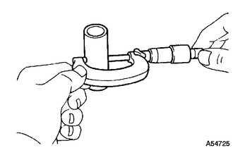
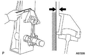
Using a rod aligner and feeler gauge, check the connecting rod alignment.
-
Check if the connecting rod is bent.
Maximum bend 0.05 mm (0.00196 in.) per 100 mm (3.94 in.) If the bend is more than the maximum, replace the connecting rod.
-
Check if the connecting rod is twisted.
Maximum twist 0.15 mm (0.00591 in.) per 100 mm (3.94 in.) If the twist is more than the maximum, replace the connecting rod.
-
-
-
INSPECT CONNECTING ROD BOLT
-
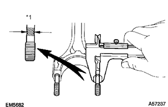
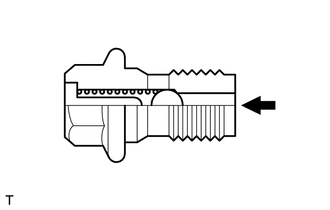
Using a vernier caliper, measure the diameter of the tension portion of the connecting rod bolt.
Standard diameter 8.400 to 8.600 mm (0.331 to 0.339 in.) Minimum diameter 8.20 mm (0.323 in.) Text in Illustration *1 Compressed Bolt If the diameter is less than the minimum, replace the bolt.
-
-
INSPECT CRANKSHAFT
-
Inspect for circle runout.
-
Place the crankshaft on V-blocks.
-
Using a dial indicator, measure the circle runout at the center journal.
Maximum circle runout 0.06 mm (0.00236 in.) If the circle runout is more than the maximum, replace the crankshaft.
-
-
Inspect the main journals and crank pins.
-
Using a micrometer, measure the diameter of each main journal and crank pin.
Standard Main Journal Diameter 61.985 to 62.000 mm (2.4403 to 2.4409 in.) Standard Crank Pin Diameter 54.988 to 55.000 mm (2.1649 to 2.1654 in.) If the diameter is not as specified, check the oil clearance. If necessary, replace the crankshaft.
-
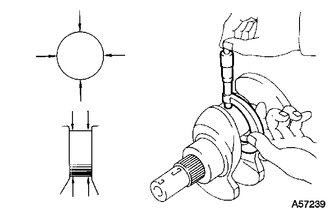
Check each main journal and crank pin for taper and out of round as shown in the illustration.
Maximum taper and out of round 0.02 mm (0.000787 in.) If the taper and out of round is more than the maximum, replace the crankshaft.
-
-
If necessary, grind and hone the main journals and/or crank pins.
-
Grind and hone the main journals and/or crank pins to the finished undersized diameter.
-
Install new main journal and/or crankshaft pin undersized bearing.
-
-
-
REMOVE CRANKSHAFT AND INSPECT OIL CLEARANCE
-
Remove the crankshaft Click here.
-
Clean each crankshaft journal and bearing.
-
Check each crankshaft journal and bearing for pitting and scratches.
If the journal or bearing is damaged, replace the bearings. If necessary, grind or replace the crankshaft.
-
Place the crankshaft on the cylinder block.
-
Text in Illustration *1 Plastigage Lay a strip of Plastigage across each journal.
-
Install the 5 crankshaft bearing caps Click here.
Note
Do not turn the crankshaft.
-
Remove the 10 bolts and 5 crankshaft bearing caps.
-
Text in Illustration *1 Plastigage Measure the Plastigage at its widest point.
Standard Oil Clearance Item Specified Condition STD 0.034 to 0.065 mm (0.00134 to 0.00256 in.) U/S 0.25, U/S 0.50 0.033 to 0.079 mm (0.00130 to 0.00311 in.) Maximum oil clearance 0.10 mm (0.00394 in.) If the oil clearance is more than the maximum, replace the bearings. If necessary, grind or replace the crankshaft.
-
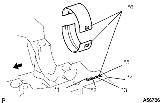
Text in Illustration *1 No. 1 *2 No. 2 *3 No. 3 *4 No. 4 *5 No. 5 *6 Mark 1, 2 or 3 Front If using a standard bearing, replace it with one having the same number marked on the connecting rod cap. There are 3 sizes of standard bearing, marked 1, 2 and 3 accordingly.
Standard Sized Bearing Center Wall Thickness Item Specified Condition Mark 1 1.979 to 1.983 mm (0.0779 to 0.0781 in.) Mark 2 1.983 to 1.987 mm (0.0781 to 0.0782 in.) Mark 3 1.987 to 1.991 mm (0.0782 to 0.0784 in.) -
Completely remove the Plastigage.
-
Perform the inspection above for each crank journal.
-
Lift out the crankshaft.
Tech Tips
Keep the upper crankshaft bearings and upper thrust washers together with the cylinder block.
-
-
INSPECT NO. 1 OIL NOZZLE
-
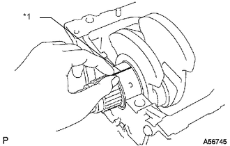
Inspect the check valve.
-
Push the valve with a wooden stick to check if it is stuck.
If stuck, replace the check valve.
-
-
Inspect the oil nozzle
-
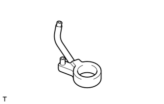
Check the oil nozzle for damage or clogging.
If necessary, replace the oil nozzle.
-
-