БЛОК ЦИЛИНДРОВ РАЗБОРКА

PROCEDURE
-
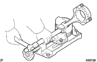
INSPECT CONNECTING ROD THRUST CLEARANCE
Tech Tips
-
Thoroughly clean all parts to be assembled.
-
Before installing the parts, apply new engine oil to all sliding and rotating surfaces.
-
Replace all gaskets, O-rings and oil seals with new ones.
-
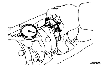
Using a dial indicator, measure the thrust clearance while moving the connecting rod back and forth.
Standard thrust clearance 0.080 to 0.300 mm (0.00315 to 0.0118 in.) Maximum thrust clearance 0.35 mm (0.0138 in.) If the thrust clearance is more than the maximum, replace the connecting rod assembly. If necessary, replace the crankshaft.
-
-
INSPECT CONNECTING ROD OIL CLEARANCE
-
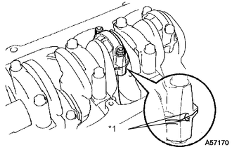
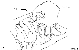
Text in Illustration *1 Matchmark Check the matchmarks on the connecting rod and cap to ensure correct reassembly.
-
Remove the 2 connecting rod cap nuts.
-
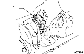
Using a plastic-faced hammer, lightly tap the connecting rod bolts and lift off the connecting rod cap.
Tech Tips
Keep the lower bearing installed to the connecting rod cap.
-
Cover the connecting rod bolts with a short piece of hose to protect the crankshaft from damage.
-
Clean the crank pin and bearing.
-
Check the crank pin and bearing for pitting and scratches.
If the crank pin or bearing is damaged, replace the bearings. If necessary, grind or replace the crankshaft.
-
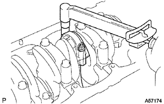
Text in Illustration *1 Plastigage Lay a strip of Plastigage across the crank pin.
-
Place the connecting rod cap on the connecting rod.
-
Match the numbered connecting rod cap with the connecting rod.
-
Text in Illustration *1 Front Mark Install the connecting rod cap with the front mark facing forward.
-
-
Install the connecting rod cap with the 2 nuts.
Tech Tips
The connecting rod cap nuts are tightened in 2 progressive steps.
If any connecting rod bolt is broken or deformed replace it.
-
Apply a light of engine oil to the threads and under the heads of the connecting rod cap nuts.
-
Step 1:
-
Install and alternately tighten the nuts of the connecting rod cap in several passes.
- Torque:
- 54 N*m { 551 kgf*cm, 40 ft.*lbf }
Note
Do not turn the crankshaft.
-
-
Step 2:
-
Mark the front of the connecting rod cap nuts with paint.
-
Retighten the connecting rod cap nuts 90° as shown step 1.
-
-
Check that the painted marks are now at a 90° angle to the front.
-
Remove the 2 nuts, connecting rod cap and lower bearing.
-
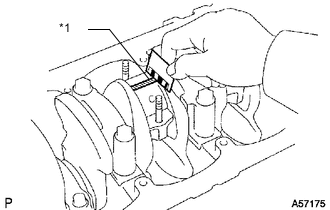
Text in Illustration *1 Plastigage Measure the Plastigage at its widest point.
Standard Oil Clearance Item Specified Condition STD 0.036 to 0.064 mm (0.00142 to 0.00252 in.) U/S 0.25, U/S 0.50 0.033 to 0.079 mm (0.00130 to 0.00311 in.) Maximum oil clearance 0.10 mm (0.00394 in.) If the oil clearance is more than the maximum, replace the bearings. If necessary, grind or replace the crankshaft.
-
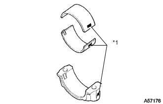
Text in Illustration *1 Mark 1, 2 or 3 If using a standard bearing, replace it with one having the same number marked on the connecting rod cap. There are 3 sizes of standard bearings, marked 1, 2 and 3 accordingly.
Standard Sized Bearing Center Wall Thickness Item Specified Condition Mark 1 1.478 to 1.482 mm (0.0582 to 0.0583 in.) Mark 2 1.482 to 1.486 mm (0.0583 to 0.0585 in.) Mark 3 1.486 to 1.490 mm (0.0585 to 0.0587 in.) -
Completely remove the Plastigage.
-
Perform the inspection above for each crank pin.
-
-
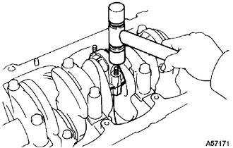
REMOVE PISTON AND CONNECTING ROD
-
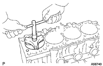
Text in Illustration *1 Ridge Reamer Using a ridge reamer, remove all the carbon from the top of the cylinder.
-
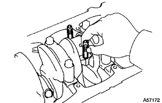
Cover the connecting rod bolts with a short piece of hose to protect the crankshaft from damage.
-
Push the piston, connecting rod and upper bearing out through the top of the cylinder block.
Tech Tips
-
Keep the bearings, connecting rod and cap together.
-
Arrange the piston and connecting rod assemblies in the correct order.
-
-
-
REMOVE PISTON SUB-ASSEMBLY
-
Check the fitting condition between the piston and piston pin.
-
Try to move the piston back and forth on the piston pin.
If any movement is felt, replace the piston and pin with a new piston and a set.
-
-
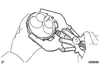
Using a piston ring expander, remove the 2 piston rings.
Tech Tips
Be sure to organize the removed piston rings in such a way that they can reinstalled exactly as before.
-
Remove the oil ring and coil by hand.
Tech Tips
Arrange the piston rings in the correct order.
-
Disconnect the connecting rod from the piston.
-
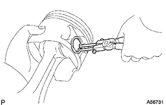
Using snap ring pliers, remove the 2 snap rings from the piston.
-
Gradually heat the piston to approximately 60°C (140°F).
-
Using a plastic-faced hammer and brass bar, lightly tap out the piston pin and remove the connecting rod.
Tech Tips
-
The piston and pin are a matched set.
-
Arrange the pistons, pins, rings, connecting rods and bearings in the correct order.
-
-
-
-
INSPECT CRANKSHAFT THRUST CLEARANCE
-
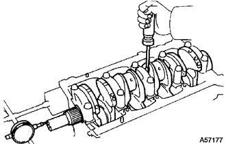
Using a dial indicator, measure the thrust clearance while prying the crankshaft back and forth with a screwdriver.
Standard thrust clearance 0.040 to 0.250 mm (0.00157 to 0.00984 in.) Maximum thrust clearance 0.30 mm (0.0118 in.) If the thrust clearance is more than the maximum, replace the thrust washers as a set.
Thrust Washer Thickness Item Specified Condition STD 2.430 to 2.480 mm (0.0957 to 0.0976 in.) O/S 0.125 2.493 to 2.543 mm (0.0981 to 0.100 in.) O/S 0.250 2.555 to 2.605 mm (0.101 to 0.103 in.)
-
-
REMOVE CRANKSHAFT
-
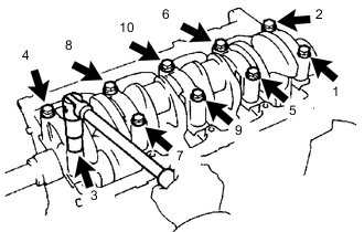
Uniformly loosen and remove the 10 crankshaft bearing cap bolts in several passes, in the sequence shown.
-
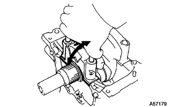
Using the removed crankshaft bearing cap bolts, pry the cap back and forth, and remove the crankshaft bearing caps, lower bearings and lower thrust washers (No. 3 crankshaft bearing cap only).
Tech Tips
-
Keep the lower bearing and crankshaft bearing caps together.
-
Be sure to organize the bearing caps and lower thrust washers in sure a way that they an be reinstalled exactly as before.
-
-
Remove the crankshaft.
-
-
REMOVE NO. 1 OIL NOZZLE SUB-ASSEMBLY
-
Remove the 4 check valves and oil nozzles.
-
-
REMOVE CYLINDER BLOCK OIL ORIFICE
-
Using a 6 mm hexagon socket wrench, remove the oil orifice.
-
-
REMOVE CYLINDER BLOCK WATER DRAIN COCK SUB-ASSEMBLY
-
Remove the water drain cock from the cylinder block.
-
-
REMOVE NO. 1 TAPER SCREW PLUG
Note
It is not necessary to remove a No. 1 taper screw plug unless it is being replaced.
-
REMOVE STUD BOLT
Note
If a stud bolt is deformed or the threads are damaged, replace it.