ГОЛОВКА БЛОКА ЦИЛИНДРОВ ЗАМЕНА

PROCEDURE
-
REPLACE INTAKE VALVE GUIDE BUSH
-
Gradually heat the cylinder head to approximately 80 to 100°C (176 to 212°F).
-
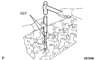
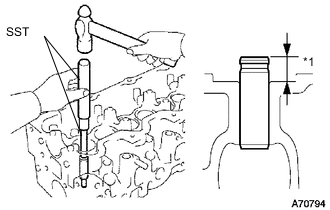
Using SST and a hammer, tap out the valve guide bush.
- SST
- 09201-10000 ( 09201-01080 )
- 09950-70010 ( 09951-07100 )
-
Using a caliper gauge, measure the bush bore diameter of the cylinder head.
-
Select a new guide bush.
New Guide Bush Item Specified Conditions Bush Bore Diameter 13.004 to 13.025 mm (0.512 to 0.513 in.) 13.054 to 13.075 mm (0.514 to 0.515 in.) Bush to be Used STD O/S 0.05 If the bush bore diameter of the cylinder head is more than 13.025 mm (0.513 in.), machine the bush bore to a dimension of 13.054 to 13.075 mm (0.514 to 0.515 in.).
If the bush bore diameter of the cylinder head is more than 13.075 mm (0.515 in.), replace the cylinder head.
-
Gradually heat the cylinder head to approximately 80 to 100°C (176 to 212°F).
-
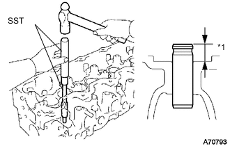
Text in Illustration *1 Protrusion Height Using SST and a hammer, tap in a new guide bush to the specified protrusion height.
- SST
- 09950-70010 ( 09951-07100 )
- 09201-10000 ( 09201-01070 )
Standard protrusion height 10.8 to 11.2 mm (0.425 to 0.441 in.) -
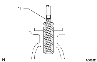
Text in Illustration *1 Reamer Using a sharp 8.0 mm reamer, ream the guide bush to obtain the specified clearance Click here.
-
-
REPLACE EXHAUST VALVE GUIDE BUSH
-
Gradually heat the cylinder head to approximately 80 to 100°C (176 to 212°F).
-
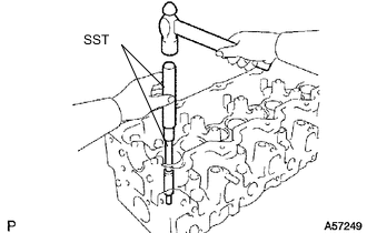
Using SST and a hammer, tap out the valve guide bush.
- SST
- 09201-10000 ( 09201-01080 )
- 09950-70010 ( 09951-07100 )
-
Using a caliper gauge, measure the bush bore diameter of the cylinder head.
-
Select a new guide bush.
New Guide Bush Item Specified Conditions Bush Bore Diameter 13.004 to 13.025 mm (0.512 to 0.513 in.) 13.054 to 13.075 mm (0.514 to 0.515 in.) Bush to be Used STD O/S 0.05 If the bush bore diameter of the cylinder head is more than 13.025 mm (0.513 in.), machine the bush bore to a dimension of 13.054 to 13.075 mm (0.514 to 0.515 in.).
If the bush bore diameter of the cylinder head is more than 13.075 mm (0.515 in.), replace the cylinder head.
-
Gradually heat the cylinder head to approximately 80 to 100°C (176 to 212°F).
-
Text in Illustration *1 Protrusion Height Using SST and a hammer, tap in a new guide bush to the specified protrusion height.
- SST
- 09950-70010 ( 09951-07100 )
- 09201-10000 ( 09201-01070 )
Standard protrusion height 10.8 mm to 11.2 mm (0.425 to 0.441 in.) -
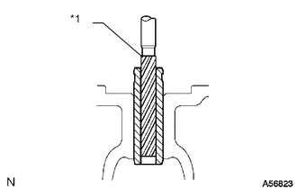
Text in Illustration *1 Reamer Using a sharp 8.0 mm reamer, ream the guide bush to obtain the specified clearance Click here.
-
-
REPLACE TIGHT PLUG
Note
If coolant leaks from the tight plug or the plug is corroded, replace it.
-
Apply adhesive to new tight plugs.
Adhesive Toyota Genuine Adhesive 1324, Three Bond 1324 or equivalent. -
Install the tight plugs as shown in the illustration.
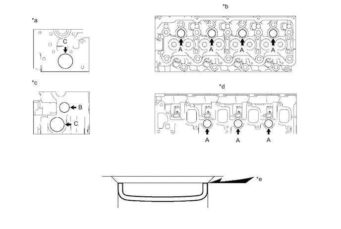
Text in Illustration *a Front Side *b Cylinder Head Cover Side *c Rear Side *d Intake Manifold Side *e Stops - - -
Using SST, tap in the 7 tight plugs labeled A.
- SST
- 09950-60010 ( 09951-00250 )
- 09950-70010 ( 09951-07100 )
-
Using SST, tap in the tight plug labeled B.
- SST
- 09950-60010 ( 09951-00300 )
- 09950-70010 ( 09951-07100 )
-
Using SST, tap in the 2 tight plugs labeled C.
- SST
- 09950-60010 ( 09951-00450 )
- 09950-70010 ( 09951-07100 )
-
-
REPLACE RING PIN
Note
It is not necessary to remove a ring pin unless it is being replaced.
-
Using a plastic-faced hammer, tap in a new ring pin until it stops.
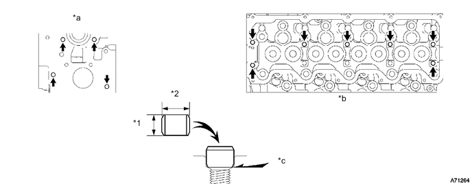
Text in Illustration *1 Height *2 Diameter *a Front Side *b Cylinder Head Cover Side *c Until pin stop - - Standard Ring Pin Item Height Diameter Ring pin 8 mm (0.315 in.) 11 mm (0.433 in.)
-