ГОЛОВКА БЛОКА ЦИЛИНДРОВ ПОВТОРНАЯ СБОРКА

PROCEDURE
-
INSTALL STUD BOLT
Note
If a stud bolt is deformed or the threads are damaged, replace it.
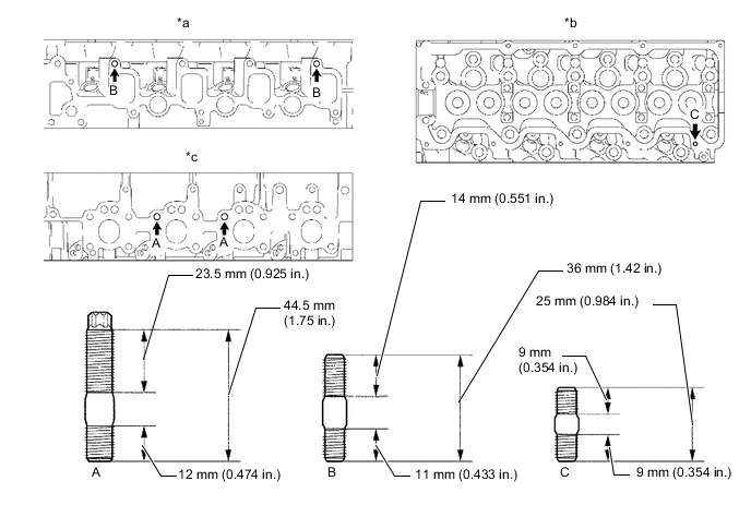
Text in Illustration *a Intake Manifold Side
B
*b Cylinder Head Cover Side *c Exhaust Manifold Side - - - Torque:
- for bolt A
- 26 N*m { 265 kgf*cm, 19 ft.*lbf }
- for bolt B
- 12 N*m { 120 kgf*cm, 9 ft.*lbf }
- for bolt C
- 6.0 N*m { 60 kgf*cm, 53 in.*lbf }
-
INSTALL SEMICIRCULAR PLUG
-
Remove any old packing (FIPG material).
-
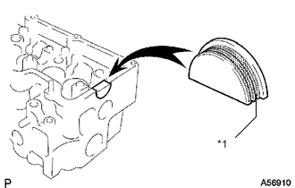
Text in Illustration *1 Seal Packing Apply seal packing to the semicircular plug as shown in the illustration.
Seal packing Toyota Genuine Seal Packing Black, Three Bond 1207B or equivalent Note
-
The semicircular plug must be installed within 3 minute from the completion of applying the seal packing.
-
Prevent FIPG from being stuck to the camshaft thrust groove.
-
-
Install the semicircular plug to the cylinder head.
-
-
INSTALL COMBUSTION CHAMBER SUB-ASSEMBLY
-
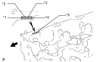
Text in Illustration *1 No. 1 Combustion Chamber *2 No. 2 Combustion Chamber *3 No. 3 Combustion Chamber *4 No. 4 Combustion Chamber *5 Mark 1, 2 or 3 
Front Select the number of shim, according to the table below.
Select a new combustion chamber Item Specified Condition Mark 1 5.91 to 5.94 mm (0.2327 to 0.2338 in.) Mark 2 5.94 to 5.97 mm (0.2338 to 0.2350 in.) Mark 3 5.97 to 6.00 mm (0.2350 to 0.2362 in.) -
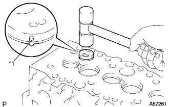
Text in Illustration *1 Pin Align the combustion chamber knock pin with the cylinder head notch.
-
Using a plastic-faced hammer, tap in the combustion chamber.
-
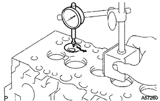
Using a dial indicator, check the combustion chamber protrusion.
Combustion chamber protrusion -0.03 to 0.03 mm (- 0.00118 to 0.00118 in.) If the protrusion is less than the specification, adjust with shims.
If the protrusion is more than the specification, replace the chamber and recheck the protrusion.
-
-
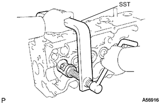
INSTALL VALVE STEM OIL SEAL
-
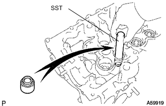
Using SST, push in a new oil seal.
- SST
- 09201-41020
-
-
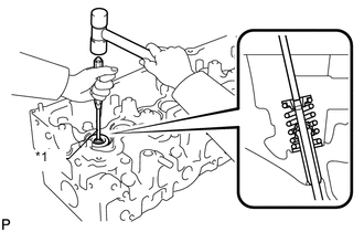
INSTALL INTAKE VALVE
-
Install the valve, spring seat plate washer, valve spring and spring retainer.
-
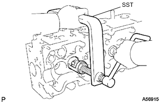
Using SST, compress the valve spring and place the 2 retainer locks around the valve stem.
- SST
- 09202-70020 ( 09202-00030 )
-
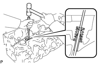
Text in Illustration *1 5 mm Pin Punch Using a 5 mm pin punch and plastic-faced hammer, lightly tap the valve stem tip to ensure a proper fit.
Note
Be careful not to damage the valve stem tip.
-
-
INSTALL EXHAUST VALVE
-
Install the valve, spring seat, valve spring and spring retainer.
-
Using SST, compress the valve spring and place the 2 retainer locks around the valve stem.
- SST
- 09202-70020 ( 09202-00030 )
-
Text in Illustration *1 5 mm Pin Punch Using a 5 mm pin punch and plastic-faced hammer, lightly tap the valve stem tip to ensure a proper fit.
Note
Be careful not to damage the valve stem tip.
-
-
INSTALL VALVE LIFTER
-
Install the valve lifter and shim.
-
Check that the valve lifter rotates smoothly by hand.
-