ГОЛОВКА БЛОКА ЦИЛИНДРОВ ПРОВЕРКА

PROCEDURE
-
CLEAN CYLINDER HEAD SUB-ASSEMBLY
-
Clean the cylinder head.
-
Using a gasket scraper, remove all the gasket material from the surface that contact the cylinder block.
Note
Do not scratch the surface that contacts the cylinder block.
-
-
Using a wire brush, remove all the carbon from the combustion chambers.
Note
Do not scratch the surface that contacts the cylinder block.
-
Using a valve guide bushing brush and solvent, clean all the guide bushes.
-
Using a soft brush and solvent, thoroughly clean the cylinder head.
-
-
INSPECT CYLINDER HEAD SUB-ASSEMBLY
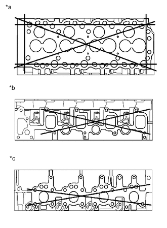
Text in Illustration *a Cylinder Block Side: *b Intake Manifold Side: *c Exhaust Manifold Side:
-
Inspect the cylinder head warpage.
-
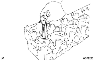
Using a precision straightedge and feeler gauge, measure the surfaces that contact the cylinder block and the manifolds for warpage.
Maximum warpage 0.20 mm (0.00787 in.) If the warpage is more than the maximum, replace the cylinder head sub-assembly.
-
-
Inspect the cylinder head for cracks.
-
Using a dye penetrant, check the combustion chamber, intake ports, exhaust ports and cylinder head surface for cracks.
If cracked, replace the cylinder head sub-assembly.
-
-
-
CLEAN VALVE
-
Using a gasket scraper, chip off any carbon from the valve head.
-
Using a wire brush, thoroughly clean the valve.
-
-
INSPECT INTAKE VALVE
-
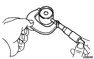
Using a micrometer, measure the diameter of the valve stem.
Standard valve stem diameter 7.975 to 7.990 mm (0.3140 to 0.3146 in.) If the diameter is not as specified, replace the intake valve.
-
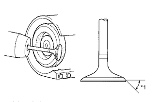
Text in Illustration *1 Valve Face Angle Check the valve face angle.
-
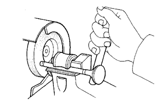
Grind the valve enough to remove any pits and carbon.
-
Check that the valve is ground to the correct valve face angle.
Standard valve face angle 44.5° If the valve is worn, replace the intake valve.
-
-
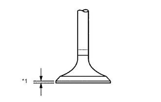
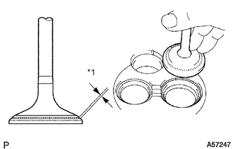
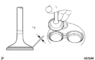
Text in Illustration *1 Margin Thickness Check the head margin thickness.
Standard margin thickness 1.6 mm (0.0630 in.) Minimum margin thickness 1.1 mm (0.0433 in.) If the margin thickness is less than the minimum, replace the intake valve.
-
Check the overall length of the valve.
Standard overall length 104.10 to 104.50 mm (4.10 to 4.11 in.) Minimum overall length 103.60 mm (4.08 in.) If the overall length is less than the minimum, replace the intake valve.
-
Check the surface of the valve stem tip for wear.
If the valve stem tip is worn, resurface the tip with a grinder or replace the intake valve.
Note
Do not grind the valve so it becomes shorter than the minimum overall length.
-
-
INSPECT EXHAUST VALVE
-
Using a micrometer, measure the diameter of the valve stem.
Standard valve stem diameter 7.960 to 7.975 mm (0.3134 to 0.3140 in.) If the diameter is not as specified, replace the exhaust valve.
-

Text in Illustration *1 Valve Face Angle Check the valve face angle.
-
Grind the valve enough to remove any pits and carbon.
-
Check that the valve is ground to the correct valve face angle.
Standard valve face angle 44.5° If the valve face is worn, replace the exhaust valve.
-
-

Text in Illustration *1 Margin Thickness Check the valve head margin thickness.
Standard margin thickness 1.7 mm (0.0669 in.) Minimum margin thickness 1.2 mm (0.0472 in.) If the margin thickness is less than the minimum, replace the exhaust valve.
-
Check the overall length of the valve.
Standard overall length 103.95 to 104.35 mm (4.09 to 4.11 in.) Minimum overall length 103.45 mm (4.07 in.) If the overall length is less than the minimum, replace the exhaust valve.
-
Check the surface of the valve stem tip for wear.
If the valve stem tip is worn, resurface the tip with a grinder or replace the exhaust valve.
Note
Do not grind the valve so it becomes shorter than the minimum overall length.
-
-
INSPECT INNER COMPRESSION SPRING
-
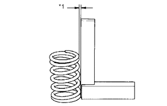
Text in Illustration *1 Deviation Using a steel square, measure the deviation of the spring.
Maximum deviation 2.0 mm (0.0787 in.) If the deviation is more than the maximum, replace the spring.
-
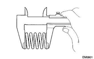
Using a vernier caliper, measure the free length of the spring.
Standard Free Length 46.20 mm (1.82 in.) If the free length is not as specified, replace the spring.
-
Using a spring tester, measure the tension of the valve spring at the installed length.
Standard tension 301 to 332 N (31 to 34 kgf, 66.6 to 74.6 lbf) at 37.00 mm (1.46 in.) If the tension is not as specified, replace the spring.
-
-
INSPECT INTAKE VALVE GUIDE BUSH
-
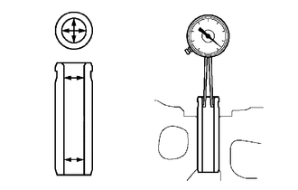
Using a caliper gauge, measure the inside diameter of the guide bush.
Standard bush inside diameter 8.010 to 8.030 mm (0.315 to 0.316 in.) -
Subtract the valve stem diameter measurement from the guide bush inside diameter measurement.
Standard oil clearance 0.020 to 0.055 mm (0.000787 to 0.00217 in.) Maximum oil clearance 0.08 mm (0.00315 in.) If the clearance is more than the maximum, replace the intake valve and guide bush.
-
-
INSPECT EXHAUST VALVE GUIDE BUSH
-
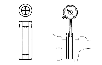
Using a caliper gauge, measure the inside diameter of the guide bush.
Standard bush inside diameter 8.010 to 8.030 mm (0.315 to 0.316 in.) -
Subtract the valve stem diameter measurement from the guide bush inside diameter measurement.
Standard oil clearance 0.035 to 0.070 mm (0.00138 to 0.00276 in.) Maximum oil clearance 0.10 mm (0.00394 in.) If the clearance is more than the maximum, replace the exhaust valve and guide bush.
-
-
INSPECT VALVE SEAT
-
Text in Illustration *1 45° Carbide Cutter Using a 45° carbide cutter, resurface the valve seats. Remove only enough metal to clean the seats.
-
Text in Illustration *1 Width Check the valve seating position.
-
Apply a light coat of Prussian blue to the valve face.
-
Lightly press the valve against the seat. Do not rotate valve.
-
Prussian blue appears 360° around the entire valve face, the valve is concentric. If not, replace the valve.
-
Prussian blue appears 360° around the entire valve seat, the guide and face are concentric. If not, resurface the seat.
-
Check that the seat contacts the middle of the valve face with the width below:
Standard width 1.5 to 1.9 mm (0.0591 to 0.0748 in.)
-
-
-
INSPECT EXHAUST VALVE SEATS
-
Using a 45° carbide cutter, resurface the valve seats. Remove only enough metal to clean the seats.
-
Text in Illustration *1 Width Check the valve seating position.
-
Apply a light coat of Prussian blue to the valve face.
-
Lightly press the valve against the seat. Do not rotate valve.
-
Prussian blue appears 360° around the entire valve face, the valve is concentric. If not, replace the valve.
-
Prussian blue appears 360° around the entire valve seat, the guide and face are concentric. If not, resurface the seat.
-
Check that the seat contacts the middle of the valve face with the width below:
Standard width 1.8 to 2.2 mm (0.0708 to 0.0866 in.)
-
-
-
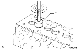
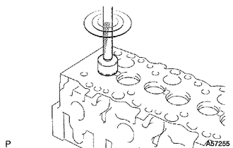
INSPECT VALVE LIFTER
-
Using a micrometer, measure the lifter diameter.
Standard lifter diameter 40.892 to 40.902 mm (1.6099 to 1.6103 in.) -
Using a caliper gauge, measure the lifter bore diameter of the cylinder head.
Standard lifter bore diameter 40.960 to 40.980 mm (1.6126 to 1.6134 in.) -
Subtract the lifter diameter measurement from the lifter bore diameter measurement.
Standard oil clearance 0.058 to 0.088 mm (0.00238 to 0.00346 in.) Maximum oil clearance 0.10 mm (0.00394 in.) If the oil clearance is more than the maximum, replace the lifter. If necessary, replace the cylinder head.
-
-
INSPECT CAMSHAFT OIL CLEARANCE
-
Inspect the journal diameter of the camshaft.
-
Using a micrometer, measure the journal diameter of the camshaft for the camshaft bearing.
Standard Journal Diameter Item Specified Condition No. 1 journal 34.969 to 34.985 mm (1.3767 to 1.3774 in.) Other journals 27.969 to 27.985 mm (1.101 to 1.102 in.) If the journal diameter is not as specified, check the oil clearance.
-
-
Text in Illustration *1 Plastigage Check the oil clearance.
-
Clean the bearing caps and journals.
-
Check the bearings for flaking and scoring.
If the bearings are damaged, replace the bearing caps and cylinder head as a set.
-
Install the bearings to the bearing caps and cylinder head.
-
Place the camshaft on the cylinder head.
-
Lay a strip of Plastigage across each of the journals.
-
Install the bearing caps Click here.
Note
Do not turn the camshaft.
-
Remove the bearing caps Click here.
-
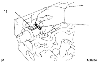
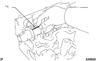
Text in Illustration *1 Plastigage Measure the Plastigage at its widest point.
Standard oil clearance 0.022 to 0.074 mm (0.000866 to 0.00291 in.) Maximum oil clearance 0.10 mm (0.00394 in.) If the oil clearance is more than the maximum, replace the cylinder head sub-assembly. If necessary, grind or replace the camshaft.
-
Completely remove the Plastigage.
-
Remove the camshaft.
-
-
-
INSPECT CAMSHAFT THRUST CLEARANCE
-
Check the thrust clearance.
-
Install the camshaft.
-
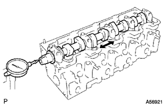
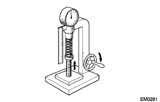
Using a dial indicator, measure the thrust clearance while moving the camshaft back and forth.
Standard thrust clearance 0.080 to 0.280 mm (0.00351 to 0.0110 in.) Maximum thrust clearance 0.35 mm (0.0138 in.) If the thrust clearance is more than the maximum, replace the No. 1 bearing. If necessary, replace the camshaft.
-
-