ПРОКЛАДКА ГОЛОВКИ БЛОКА ЦИЛИНДРОВ УСТАНОВКА
PROCEDURE
-
INSTALL CYLINDER HEAD GASKET
-
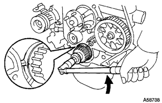
Check the piston protrusion for each cylinder.
-
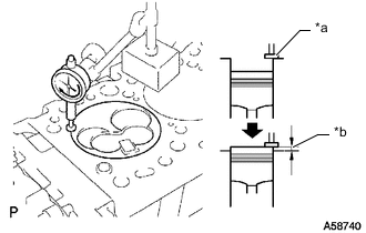
Text in Illustration *a Measuring Tip *b Protrusion Find where the piston head protrudes most by slowly turning the crankshaft clockwise and counterclockwise.
-
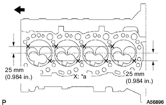
Text in Illustration *a Measuring Point 
Front Measure the protrusion of each cylinder at 2 places as shown in the illustration, making a total of 8 measurements.
-
For the piston protrusion value of each cylinder, use the average of the 2 measurements of that cylinder.
Standard protrusion 0.68 to 0.98 mm (0.0268 to 0.0386 in.) After installing the piston and connecting rod assembly, if the protrusion is not as specified, remove the piston and connecting rod assembly and reinstall them.
-
-
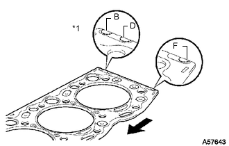
Text in Illustration *1 Cutout Mark Front Select a new cylinder head gasket.
Tech Tips
There are 3 sizes of new cylinder head gaskets, marked "B", "D" or "F" accordingly.
New Cylinder Head Gasket Thickness Item Specified Condition Mark B 1.40 to 1.50 mm (0.0551 to 0.0591 in.) Mark D 1.50 to 1.60 mm (0.0591 to 0.0630 in.) Mark F 1.60 to 1.70 mm (0.0630 to 0.0669 in.)
-
Select the largest piston protrusion value from the measurements made, then select a new appropriate gasket according to the table below.
Gasket Size Piston Protrusion Gasket Size 0.68 to 0.78 mm (0.0268 to 0.0307 in.) Use B 0.78 to 0.88 mm (0.0307 to 0.0346 in.) Use D 0.88 to 0.98 mm (0.0346 to 0.0385 in.) Use F
-
-
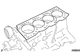
Install the selected cylinder head gasket to the cylinder block.
Note
Make sure that the gasket is installed facing the proper direction.
Be careful of the installation direction.
-
-
INSTALL CYLINDER HEAD SUB-ASSEMBLY
Tech Tips
-
The cylinder head bolts are tightened in 3 progressive steps.
-
Set the No. 1 cylinder to 90° BTDC/compression to avoid interference with the piston top and valve head.
-
If any bolt is broken or deformed, replace it.
-
Using the crankshaft pulley bolt, turn the crankshaft 90° counterclockwise, and align the timing mark of the crankshaft timing pulley with the protrusion of the timing belt case.
Text in Illustration Turn -
Place the cylinder head on the cylinder block.
Note
-
Make sure that no oil is on the mounting surface of the cylinder head.
-
Place the cylinder head on the cylinder block gently in order not to damage the gasket with the bottom part of the head.
-
-
Install the plate washers to the cylinder head bolts.
-
Apply a light coat of engine oil to the threads and under the heads of the cylinder head bolts.
-
Step 1:
-
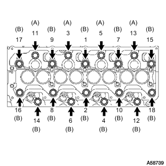
Install and uniformly tighten the 18 cylinder head bolts, in several steps, in the sequence shown in the illustrations.
- Torque:
- 78 N*m { 795 kgf*cm, 58 ft.*lbf }
Tech Tips
Each bolt length is indicated below.
Standard Bolt Item Length Bolt A 107 mm (4.21 in.) Bolt B 127 mm (5.00 in.) If any one of the cylinder head bolts does not meet the torque specification, replace the cylinder set head bolt.
-
-
Step 2:
-
Mark the front side of each cylinder head bolt head with paint.
-
Tighten the cylinder head bolts 90° in the sequence shown in step 1.
-
-
Step 3:
-
Tighten the cylinder head bolts another 90° in the sequence shown in step 1.
-
-
Check that the paint marks are now at a 180° angle to the front.
-
-
INSTALL CYLINDER HEAD COVER SUB-ASSEMBLY
-
INSTALL WIRING HARNESS CLAMP BRACKET (for LHD)
-
CONNECT WIRE HARNESS
-
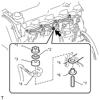
Text in Illustration *1 Nut *2 Washer *3 No. 2 Glow Plug Resistor Insulator *4 Engine Wire *5 No. 1 Glow Plug Connector *6 No. 1 Glow Plug Resistor Insulator *7 Bolt Connect the engine wire and install the No. 2 glow plug resistor insulator and washer with the nut.
- Torque:
- 5.0 N*m { 51 kgf*cm, 44 in.*lbf }
-
Attach the 4 wire harness clamps.
-
Install the generator wire with the nut.
- Torque:
- 9.8 N*m { 100 kgf*cm, 87 in.*lbf }
-
Install the terminal cap.
-
Connect the generator connector and cooler compressor connector.
-
for RHD:
-
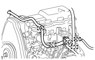
Attach the 5 wire harness clamps.
-
-
for LHD:
-
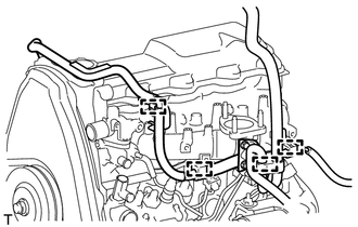
Attach the 4 wire harness clamps.
-
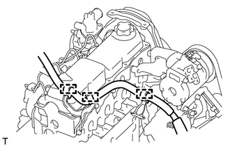
Attach the 3 wire harness clamps.
-
-
-
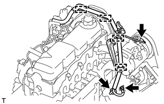
INSTALL INJECTION PIPE SET
-
INSTALL HEATER WATER HOSE SUB-ASSEMBLY
-
INSTALL NO. 1 EXHAUST MANIFOLD HEAT INSULATOR
-
INSTALL ENGINE OIL LEVEL DIPSTICK GUIDE
-
INSTALL NO. 1 COMPRESSOR MOUNTING BRACKET
-
Install the No. 1 compressor mounting bracket with the 4 bolts.
- Torque:
- 81 N*m { 829 kgf*cm, 60 ft.*lbf }
-
Connect the generator with the bolt.
-
-
CONNECT COOLER COMPRESSOR ASSEMBLY
-
INSTALL DIESEL THROTTLE BODY ASSEMBLY
-
Install the diesel throttle body Click here.
-
-
INSTALL TIMING BELT
-
Install the timing belt Click here.
-
-
INSTALL FRONT EXHAUST PIPE ASSEMBLY (for Long Wheelbase)
-
BLEED AIR FROM FUEL SYSTEM
-
ADD ENGINE COOLANT
-
BLEED INJECTION PIPE
-
INSPECT FOR COOLANT LEAK
-
INSPECT FOR FUEL LEAK
-
INSPECT FOR EXHAUST GAS LEAK
-
INSPECT ENGINE IDLE SPEED
-
INSPECT MAXIMUM ENGINE SPEED