РАСПРЕДВАЛ УСТАНОВКА

PROCEDURE
-
INSTALL CAMSHAFT
-
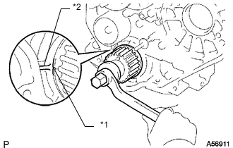
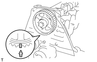
Text in Illustration *1 Timing Mark *2 Protrusion Check that the timing mark of the crankshaft timing pulley is in the position shown in the illustration.
-
Install the camshaft.
-
Place the camshaft on the cylinder head with the key groove facing upward.
-
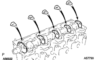
Install the 5 bearing caps in their proper locations.
-
Apply a light coat of engine oil to the threads and under the heads of the bearing cap bolts.
-
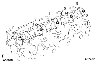
Install and uniformly tighten the 10 bearing cap bolts in several steps in the sequence shown in the illustration.
- Torque:
- 25 N*m { 255 kgf*cm, 18 ft.*lbf }
-
-
-
INSTALL CAMSHAFT OIL SEAL
-
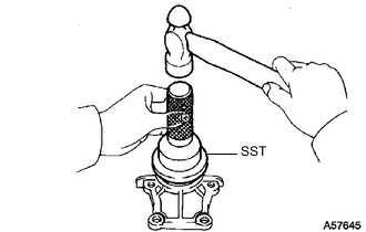
Using SST and a hammer, tap in a new oil seal until its surface is flush with the oil seal retainer edge.
- SST
- 09960-10010 ( 09962-01000, 09963-01000 )
-
Apply MP grease to the lip of the oil seal.
-
-
INSTALL CAMSHAFT OIL SEAL RETAINER
-
Install a new gasket and the retainer with the 4 bolts.
- Torque:
- 18 N*m { 184 kgf*cm, 13 ft.*lbf }
-
-
INSTALL NO. 2 TIMING BELT COVER
-
Install the timing belt cover with the 4 bolts.
- Torque:
- 18 N*m { 184 kgf*cm, 13 ft.*lbf }
-
-
INSTALL CAMSHAFT TIMING PULLEY
-
Install the woodruff key to the key groove of the camshaft.
-
Align the timing mark on the camshaft timing pulley with the timing mark on the No. 2 timing belt cover and temporarily install the pulley with the bolt.
-
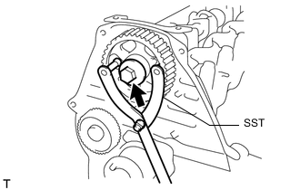
Using SST, tighten the bolt.
- SST
- 09960-10010 ( 09962-01000, 09963-01000 )
- Torque:
- 98 N*m { 999 kgf*cm, 72 ft.*lbf }
-
-
SET NO. 1 CYLINDER TO TDC/COMPRESSION
-
INSTALL TIMING BELT
-
CHECK NO. 1 CYLINDER TO TDC/COMPRESSION
-
INSTALL TIMING BELT GUIDE
-
INSPECT VALVE CLEARANCE
-
ADJUST VALVE CLEARANCE
-
INSTALL CYLINDER HEAD COVER SUB-ASSEMBLY
-
INSTALL INTAKE PIPE
-
INSTALL TIMING BELT COVER
-
INSTALL IDLE PULLEY ASSEMBLY
-
INSTALL CRANKSHAFT PULLEY
-
INSTALL VANE PUMP DRIVE PULLEY
-
INSTALL FAN SHROUD
-
INSTALL RADIATOR RESERVE TANK ASSEMBLY
-
INSTALL NO. 1 RADIATOR HOSE
-
INSTALL WIRING HARNESS CLAMP BRACKET (for LHD)
-
CONNECT WIRE HARNESS
-
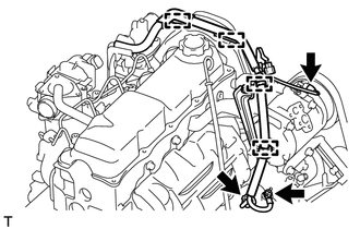
Attach the 4 wire harness clamps.
-
Install the generator wire with the nut.
- Torque:
- 9.8 N*m { 100 kgf*cm, 87 in.*lbf }
-
Install the terminal cap.
-
Connect the generator connector and cooler compressor connector.
-
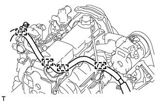
for LHD:
Attach the 4 wire harness clamps.
-
-
INSTALL AIR CLEANER CASE ASSEMBLY
-
INSTALL AIR CLEANER FILTER ELEMENT SUB-ASSEMBLY
-
INSTALL RESONATOR WITH AIR CLEANER CAP SUB-ASSEMBLY
-
INSTALL FRONT FENDER APRON SEAL RH
-
ADD ENGINE COOLANT
-
CONNECT CABLE TO NEGATIVE BATTERY TERMINAL
Note
When disconnecting the cable, some systems need to be initialized after the cable is reconnected Click here.
-
INSPECT FOR ENGINE COOLANT LEAK
-
INSPECT ENGINE IDLE SPEED
-
INSPECT MAXIMUM ENGINE SPEED
-
INSTALL NO. 1 ENGINE UNDER COVER SUB-ASSEMBLY
-
INSTALL FRONT BUMPER COVER LOWER
-
INSTALL UPPER RADIATOR SUPPORT SEAL