ДВИГАТЕЛЬ В СБОРЕ СНЯТИЕ

PROCEDURE
-
DISCONNECT CABLE FROM NEGATIVE BATTERY TERMINAL
Note
-
After turning the ignition switch off, waiting time may be required before disconnecting the cable from the battery terminal. Therefore, make sure to read the disconnecting the cable from the battery terminal notice before proceeding with work Click here.
-
When disconnecting the cable, some systems need to be initialized after the cable is reconnected Click here.
-
-
REMOVE BATTERY HOLD DOWN CLAMP
-
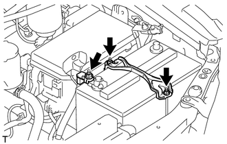
Remove the nut and disconnect the engine wire.
-
Remove the 2 nuts and battery hold down clamp.
-
-
REMOVE BATTERY
-
REMOVE BATTERY TRAY
-
REMOVE HOOD SUB-ASSEMBLY
-
Disconnect the washer nozzle hose.
-
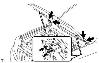
Remove the 8 bolts and hood.
Note
If the hood support is detached from the ball joint, it become non-reusable. Therefore, do not detach the hood support from the ball joint unless replacing it.
-
-
REMOVE COWL TOP VENTILATOR LOUVER SUB-ASSEMBLY
-
Remove the cowl top ventilator louver Click here.
-
-
REMOVE UPPER RADIATOR SUPPORT SEAL
-
REMOVE FRONT BUMPER COVER LOWER
-
Remove the clip, 5 bolts and front bumper cover lower.
-
-
REMOVE NO. 1 ENGINE UNDER COVER SUB-ASSEMBLY
-
Remove the 4 bolts.
-
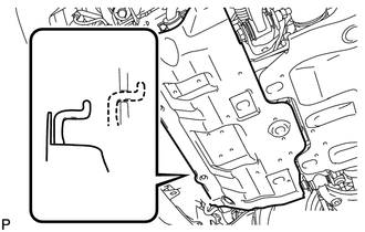
Unhook the engine under cover from the vehicle body as shown in the illustration.
-
-
REMOVE TRANSMISSION UNDER COVER
-
Remove the 2 bolts and transmission under cover.
-
-
REMOVE REAR ENGINE UNDER COVER ASSEMBLY
-
Remove the 4 bolts and rear engine under cover.
-
-
DRAIN ENGINE COOLANT
-
DRAIN ENGINE OIL
-
REMOVE FRONT FENDER APRON SEAL RH
-
Remove the 4 clips and fender apron seal.
-
-
REMOVE NO. 1 FRONT FENDER APRON TO FRAME SEAL RH
-
Remove the 5 clips and frame seal.
-
-
REMOVE FRONT FENDER APRON SEAL LH
-
Remove the 5 clips and fender apron seal.
-
-
REMOVE NO. 1 FRONT FENDER APRON TO FRAME SEAL LH
-
Remove the 5 clips and frame seal.
-
-
REMOVE RESONATOR WITH AIR CLEANER CAP SUB-ASSEMBLY
-
REMOVE AIR CLEANER FILTER ELEMENT SUB-ASSEMBLY
-
REMOVE AIR CLEANER CASE ASSEMBLY
-
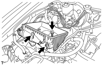
Remove the 3 bolts and air cleaner case.
-
-
REMOVE FRONT BUMPER COVER
-
REMOVE FRONT UPPER BUMPER RETAINER
-
REMOVE RADIATOR SIDE DEFLECTOR LH
-
REMOVE RADIATOR SIDE DEFLECTOR RH
-
REMOVE NO. 1 RADIATOR HOSE
-
REMOVE NO. 2 RADIATOR HOSE
-
REMOVE FAN SHROUD
-
REMOVE RADIATOR ASSEMBLY
-
REMOVE INTAKE PIPE ASSEMBLY
-
DISCONNECT COOLER COMPRESSOR ASSEMBLY
-
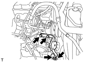
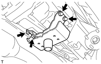
Remove the 4 bolts and idle pulley bracket.
-
Disconnect the connector.
-
Remove the 3 bolts and disconnect the cooler compressor.
Tech Tips
It is not necessary to completely remove the cooler compressor. With the hoses connected to the compressor, hang the compressor on the vehicle body with a rope.
-
-
REMOVE GENERATOR ASSEMBLY
-
REMOVE GLOVE COMPARTMENT DOOR ASSEMBLY
-
Remove the glove compartment door Click here.
-
-
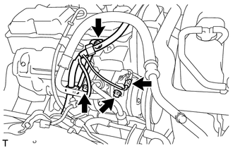
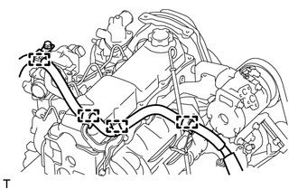
DISCONNECT ENGINE WIRE
-
Remove the 3 bolts, detach the clamp and disconnect the engine wire.
-
Remove the No. 1 relay block cover.
-
Remove the nut and detach the 2 claws.
-
Disconnect the connector.
-
Detach the 2 clamps and disconnect the engine wire.
-
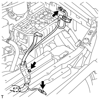
for LHD:
Detach the 4 clamps.
-
Text in Illustration *A for LHD *B for RHD Detach the grommet from the wire harness support.
-
Text in Illustration *A for LHD *B for RHD Detach the 4 claws to remove the wire harness support from the vehicle, and then pull out the ECM connector to remove it from the vehicle.
-
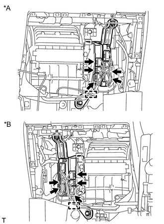
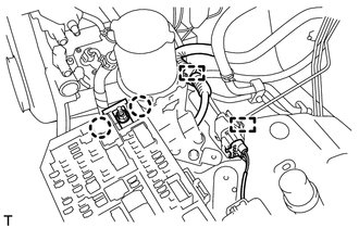
Text in Illustration *A for LHD *B for RHD Detach the clamp and disconnect the 5 connectors as shown in the illustration.
-
-
REMOVE WIRING HARNESS CLAMP BRACKET (for LHD)
-
Remove the bolt and wiring harness clamp bracket.
-
-
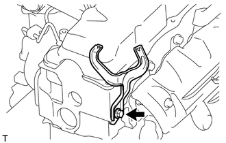
DISCONNECT HEATER WATER HOSE ASSEMBLY
-
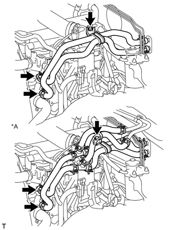
Text in Illustration *A for Rear Heater Remove the bolt and disconnect the heater water hoses.
-
-
LOOSEN FUEL TANK CAP ASSEMBLY
-
DRAIN FUEL
-
DISCONNECT FUEL HOSE
-
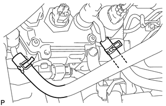
Disconnect the 2 fuel hoses.
-
-
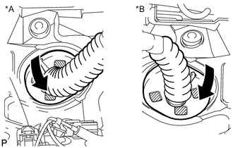
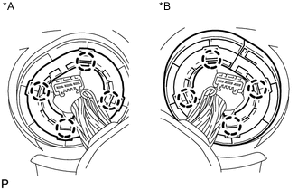
DISCONNECT VANE PUMP ASSEMBLY
-
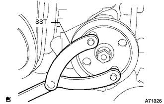
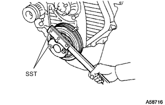
Using SST, hold the pulley and loosen the nut.
- SST
- 09960-10010 ( 09962-01000, 09963-01000 )
-
Remove the nut and vane pump pulley from the vane pump shaft.
-
Remove the 2 bolts and nut and disconnect the vane pump.
Tech Tips
Disconnect the vane pump from the vehicle with the hoses connected, and hang it with a rope.
-
-
REMOVE CLUTCH RELEASE CYLINDER ASSEMBLY
-
REMOVE STARTER ASSEMBLY
-
REMOVE OIL FILTER SUB-ASSEMBLY
-
REMOVE FRONT EXHAUST PIPE ASSEMBLY
-
REMOVE FRONT PROPELLER SHAFT ASSEMBLY
-
REMOVE PROPELLER SHAFT ASSEMBLY
-
REMOVE MANUAL TRANSMISSION ASSEMBLY
-
Remove the manual transmission Click here.
-
-
REMOVE REAR NO. 1 ENGINE MOUNTING INSULATOR
Note
Perform this procedure when replacement of the engine mounting insulator is necessary.
-
Remove the 4 bolts and rear engine mounting insulator from the transmission.
-
-
REMOVE CLUTCH COVER ASSEMBLY
-
REMOVE CLUTCH DISC ASSEMBLY
-
REMOVE FLYWHEEL SUB-ASSEMBLY
-
Using SST, hold the crankshaft.
- SST
- 09213-54015 ( 91651-60855 )
- 09330-00021
-
Remove the 8 bolts and flywheel.
-
-
REMOVE REAR END PLATE
-
Remove the 2 bolts and rear end plate.
-
-
REMOVE FLYWHEEL HOUSING DUST SEAL
-
INSTALL ENGINE HANGER
-
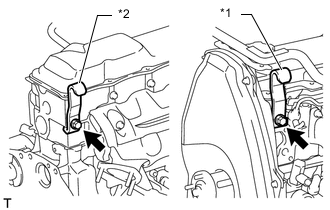
Text in Illustration *1 No. 1 Engine Hanger *2 No. 2 Engine Hanger Install an engine hanger to each location shown in the illustration.
Tech Tips
No. 1 Engine Hanger 12281-54080 No. 2 Engine Hanger 12282-54070 Bolt (No. 1 Engine Hanger) 90119-10736 Bolt (No. 2 Engine Hanger) 91622-61022 - Torque:
- for No. 1 Engine Hanger
- 59 N*m { 602 kgf*cm, 44 ft.*lbf }
- for No. 2 Engine Hanger
- 37 N*m { 377 kgf*cm, 27 ft.*lbf }
Note
Install the engine hangers with new bolts.
-
-
REMOVE ENGINE ASSEMBLY
-
Attach an engine sling device and hang the engine with a chain block.
-
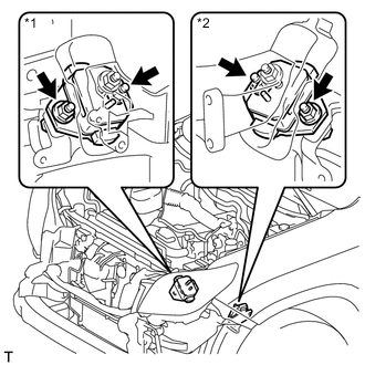
Text in Illustration *1 for RH Side *2 for LH Side Remove the 4 nuts and 4 bolts from the front engine mounting insulator LH and RH.
-
Remove the engine by operating the engine sling device and chain block.
-
-
INSTALL ENGINE TO ENGINE STAND
-
Install the engine to an engine stand with bolts.
-
Remove engine hanger.
-
-
REMOVE ENGINE WIRE
-
Remove the engine wire from the engine.
-
-
REMOVE FRONT ENGINE MOUNTING INSULATOR
-
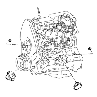
Remove the 2 nuts and 2 front engine mounting insulators.
-