СИСТЕМА ECD Air Conditioning Signal Circuit
DESCRIPTION
When the A/C compressor is on, the A/C amplifier sends the A/C signal to the ECM and the ECM increases the fuel injection volume to improve driveability during engine idling.
WIRING DIAGRAM
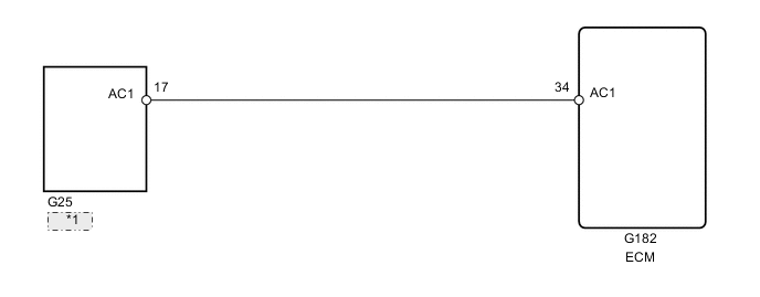
| *1 | A/C ECU |
PROCEDURE
-
READ VALUE USING GTS (AIR CONDITIONING SIGNAL)
-
Connect the GTS to the DLC3.
-
Start the engine.
-
Turn the A/C switch on.
-
Enter the following menus: Powertrain / Engine and ECT / Data List / A/C SIG.
Result Switch Condition A/C SIG A/C switch off OFF A/C switch on ON
OK 
PROCEED TO NEXT SUSPECTED AREA SHOWN IN PROBLEM SYMPTOMS TABLE Click here
NG 
-
-
CHECK ECM (AC1 VOLTAGE)
-
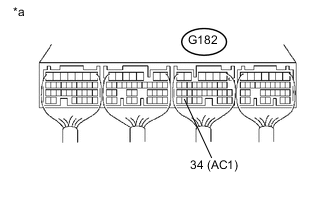
Text in Illustration *a Component with harness connected
(ECM)
Start the engine.
-
Measure the voltage according to the value(s) in the table below.
Standard Voltage Tester Connection Switch Condition Specified Condition G182-34 (AC1) - Body ground A/C switch on Below 1.5 V G182-34 (AC1) - Body ground A/C switch off 7.5 to 14 V
OK
REPLACE ECM Click here
NG
-
-
CHECK HARNESS AND CONNECTOR (ECM - AIR CONDITIONING AMPLIFIER)
-
Disconnect the A/C amplifier connector.
-
Disconnect the ECM connector.
-
Measure the resistance according to the value(s) in the table below.
Standard Resistance Tester Connection Condition Specified Condition G25-17 (AC1) - G182-34 (AC1) Always Below 1 Ω G25-17 (AC1) or G182-34 (AC1) - Body ground Always 10 kΩ or higher -
Reconnect the A/C amplifier connector.
-
Reconnect the ECM connector.
OK
REPLACE AIR CONDITIONING AMPLIFIER Click here
NG
REPAIR OR REPLACE HARNESS OR CONNECTOR
-