СИСТЕМА ECD Pre-heating Control Circuit
DESCRIPTION
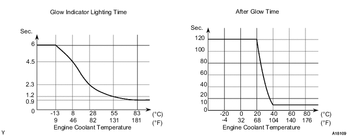
When the ignition switch is turned to ON, the ECM calculates the glow indicator lighting time/heating corresponding to the coolant temperature at that time and turns on the glow indicator light/glow plug relay (GLOW).
As ceramic is used for glow plug assembly material, current control is not performed.
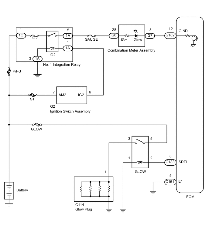
WIRING DIAGRAM
CAUTION / NOTICE / HINT
Note
Inspect the fuses for circuits related to this system before performing the following inspection procedure.
PROCEDURE
-
CHECK GLOW INDICATOR LIGHT
-
Turn the ignition switch to ON.
-
Check that the glow indicator light comes on.
OK The glow indicator light remains on for 0.5 seconds or more, and then goes off.
NG 
CHECK ECM (GIND VOLTAGE) Click here
OK 
-
-
CHECK GLOW PLUG ASSEMBLY (INSTALLATION)
-
Check that the glow plug assembly and glow plug wire are securely installed.
OK The glow plug assembly and glow plug wire are securely installed.
NG 
TIGHTEN GLOW PLUG ASSEMBLY
OK
-
-
INSPECT GLOW PLUG ASSEMBLY (RESISTANCE)
-
Inspect the glow plug assembly Click here.
NG
REPLACE GLOW PLUG ASSEMBLY Click here
OK
-
-
CHECK INDICATOR LIGHTING TIME AND AFTER GLOW TIME
NG
REPLACE ECM Click here
OK
-
READ OUTPUT DTC
-
Connect the GTS to the DLC3.
-
Turn the ignition switch to ON and turn the GTS on.
-
Enter the following menus: Powertrain / Engine and ECT / DTC.
-
Read the DTCs Click here.
Result Result Proceed to DTC is not output A DTC is output B
B
GO TO RELEVANT DTC CHART Click here
A
-
-
INSPECT GLOW RELAY ASSEMBLY
-
Inspect the glow plug relay (GLOW) Click here.
NG
REPLACE GLOW PLUG RELAY (GLOW)
OK
-
-
CHECK ECM (SREL VOLTAGE)
-
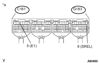
Text in Illustration *a Component with harness connected
(ECM)
Turn the ignition switch to the start position.
-
Measure the voltage according to the value(s) in the table below.
Standard Voltage Tester Connection Condition Specified Condition G183-8 (SREL) - C161-5 (E1) Cranking 11 to 14 V
NG
REPLACE ECM Click here
OK
-
-
CHECK HARNESS AND CONNECTOR (GLOW RELAY - ECM AND BODY GROUND)
-
Disconnect the ECM connector.
-
Remove the glow relay from the engine room relay block.
-
Measure the resistance according to the value(s) in the table below.
Standard Resistance Tester Connection Condition Specified Condition G183-8 (SREL) - Relay block glow relay terminal 2 Always Below 1 Ω Relay block glow relay terminal 1 - Body ground Always Below 1 Ω G183-8 (SREL) or relay block glow relay terminal 2 - Body ground Always 10 kΩ or higher -
Reconnect the ECM connector.
-
Reinstall the glow relay.
NG
REPAIR OR REPLACE HARNESS OR CONNECTOR
OK
-
-
CHECK HARNESS AND CONNECTOR (GLOW PLUG RELAY (GLOW) - GLOW PLUG ASSEMBLY AND BATTERY)
-
Disconnect the cable from the negative (-) battery terminal.
-
Disconnect the cable from the positive (+) battery terminal.
-
Remove the glow relay from the engine room relay block.
-
Disconnect the glow plug wire.
-
Measure the resistance according to the value(s) in the table below.
Standard Resistance Tester Connection Condition Specified Condition Relay block glow relay terminal 3 - C114-1 Always Below 1 Ω Relay block glow relay terminal 5 - Positive (+) battery terminal Always Below 1 Ω Note
After reconnecting the battery cable, the radio and clock need to be adjusted as they were previously.
-
Reinstall the glow relay.
-
Reconnect the glow plug wire.
-
Reconnect the cable to the positive (+) battery terminal.
-
Reconnect the cable to the negative (-) battery terminal.
OK
PROCEED TO NEXT SUSPECTED AREA SHOWN IN PROBLEM SYMPTOMS TABLE Click here
NG
REPAIR OR REPLACE HARNESS OR CONNECTOR
-
-
CHECK ECM (GIND VOLTAGE)
-
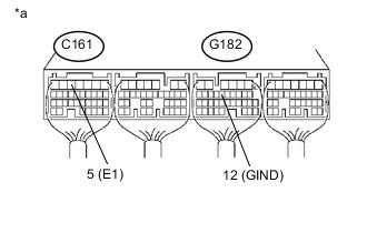
Text in Illustration *a Rear view of wire harness connector
(to ECM)
Disconnect the ECM connector.
-
Turn the ignition switch to ON.
-
Measure the voltage according to the value(s) in the table below.
Standard Voltage Tester Connection Switch Condition Specified Condition G182-12 (GIND) - C161-5 (E1) Ignition switch ON 11 to 14 V -
Reconnect the ECM connector.
OK
REPLACE ECM Click here
NG
-
-
CHECK HARNESS AND CONNECTOR (ECM - COMBINATION METER ASSEMBLY)
-
Disconnect the combination meter assembly connector.
-
Disconnect the ECM connector.
-
Measure the resistance according to the value(s) in the table below.
Standard Resistance Tester Connection Condition Specified Condition G7-8 - G182-12 (GIND) Always Below 1 Ω -
Reconnect the combination meter assembly connector.
-
Reconnect the ECM connector.
NG
REPAIR OR REPLACE HARNESS OR CONNECTOR
OK
-
-
CHECK HARNESS AND CONNECTOR (COMBINATION METER ASSEMBLY - BATTERY)
-
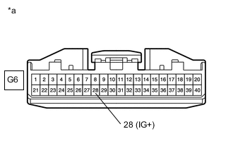
Text in Illustration *a Front view of wire harness connector
(to Combination Meter Assembly)
Disconnect the combination meter assembly connector.
-
Turn the ignition switch to ON.
-
Measure the voltage according to the value(s) in the table below.
Standard Voltage Tester Connection Switch Condition Specified Condition G6-28 - Body ground Ignition switch ON 11 to 14 V -
Reconnect the combination meter assembly connector.
OK
REPLACE COMBINATION METER ASSEMBLY Click here
NG
REPAIR OR REPLACE HARNESS OR CONNECTOR
-