СИСТЕМА ECD, Diagnostic DTC:P0105
| DTC Code | DTC Name |
|---|---|
| P0105 | Manifold Absolute Pressure / Barometric Pressure Circuit |
DESCRIPTION
The manifold absolute pressure sensor generates voltage by the vacuum value as shown in the illustration. This voltage of the manifold absolute pressure sensor is one of the factors used to decide the injection volume and injection timing.

| DTC No. | DTC Detection Condition | Trouble Area |
|---|---|---|
| P0105 | Open or short in manifold absolute pressure sensor circuit for 2 seconds or more. |
|
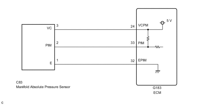
WIRING DIAGRAM
CAUTION / NOTICE / HINT
Tech Tips
Read freeze frame data using the GTS. Freeze frame data records the engine condition when malfunctions are detected. When troubleshooting, freeze frame data can help determine if the vehicle was moving or stationary, if the engine was warmed up or not, and other data from the time the malfunction occurred.
PROCEDURE
-
READ VALUE USING GTS (MAP)
-
Connect the GTS to the DLC3.
-
Turn the ignition switch to ON and turn the GTS on.
-
Enter the following menus: Powertrain / Engine and ECT / Data List / MAP.
-
Read the value.
OK The same as atmospheric pressure. Tech Tips
Standard atmospheric pressure is 101 kPa. For every 100 m increase in elevation, pressure drops by 1 kPa. This varies by weather (high atmospheric pressure, low atmospheric pressure).
Intake Manifold Pressure (kPa) Malfunction Approx. 0
-
Open in VC circuit
-
Short in PIM circuit
192 or more
-
Open in PIM circuit
-
Open in E2 circuit
-
NG 
CHECK HARNESS AND CONNECTOR (ECM - MANIFOLD ABSOLUTE PRESSURE SENSOR) Click here
OK 
-
-
CHECK CONNECTION OF VACUUM HOSE
-
Check that the vacuum hose is securely connected and there are no leaks from the connection.
OK The vacuum hose is securely connected and there are no leaks from the connection.
NG 
REPAIR OR REPLACE VACUUM HOSE
OK
-
-
CHECK HARNESS AND CONNECTOR (ECM - MANIFOLD ABSOLUTE PRESSURE SENSOR)
-
Disconnect the manifold absolute pressure sensor connector.
-
Disconnect the ECM connector.
-
Measure the resistance according to the value(s) in the table below.
Standard Resistance Tester Connection Condition Specified Condition C83-2 (PIM) - G183-33 (PIM) Always Below 1 Ω C83-3 (VC) - G183-24 (VCPM) Always Below 1 Ω C83-1 (E) - G183-32 (EPIM) Always Below 1 Ω C83-2 (PIM) or G183-33 (PIM) - Body ground Always 10 kΩ or higher C83-3 (VC) or G183-24 (VCPM) - Body ground Always 10 kΩ or higher
NG
REPAIR OR REPLACE HARNESS OR CONNECTOR
OK
-
-
INSPECT ECM (CHECK VOLTAGE)
-
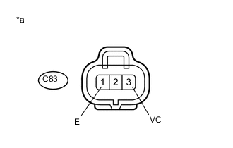
Text in Illustration *a Front view of wire harness connector
(to Manifold Absolute Pressure Sensor)
Disconnect the manifold absolute pressure sensor connector.
-
Measure the voltage according to the value(s) in the table below.
Standard Voltage Tester Connection Switch Condition Specified Condition C83-3 (VC) - C83-1 (E) Ignition switch ON 4.5 to 5.5 V
NG
REPLACE ECM Click here
OK
-
-
REPLACE MANIFOLD ABSOLUTE PRESSURE SENSOR
-
Replace the manifold absolute pressure sensor.
NEXT
-
-
READ OUTPUT DTC (DTC P0105 IS OUTPUT AGAIN)
-
Connect the GTS to the DLC3.
-
Turn the ignition switch to ON and turn the GTS on.
-
Clear the DTC Click here.
-
Turn the ignition switch to ON.
-
Check the DTC Click here.
Result Display (DTC output) Proceed to DTC P0105 is output again A No DTC output B
A
REPLACE ECM Click here
B
END
-