СИСТЕМА ECD, Diagnostic DTC:P0500
| DTC Code | DTC Name |
|---|---|
| P0500 | Vehicle Speed Sensor |
DESCRIPTION
The vehicle speed sensor outputs a 4 pulse signal for every revolution of the rotor shaft, which is rotated by the transmission output shaft via the driven gear. After this signal is converted into a more precise rectangular waveform by the waveform shaping circuit inside the combination meter assembly, it is then transmitted to the ECM. The ECM determines the vehicle speed based on the frequency of these pulse signals.
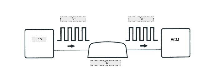
| *a | 4-Pulse Signal |
| *b | Speed Sensor |
| *c | Combination Meter |
| DTC No. | DTC Detection Condition | Trouble Area |
|---|---|---|
| P0500 | All conditions below are detected continuously for 8 second or more:
|
|
MONITOR DESCRIPTION
The ECM assumes that the vehicle is being driven when the indicated engine speed is 2000 to 3300 rpm and the engine load calculated by the ECM is more than a certain level. If there is no signal from the speed sensor, despite these conditions being met, the ECM interprets this as a malfunction in the speed signal circuit. The ECM then illuminates the MIL and stores the DTC.
WIRING DIAGRAM
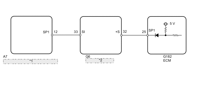
| *1 | Skid Control ECU (Brake Actuator) |
| *2 | Combination Meter |
CAUTION / NOTICE / HINT
Tech Tips
Read freeze frame data using the GTS. Freeze frame data records the engine condition when malfunctions are detected. When troubleshooting, freeze frame data can help determine if the vehicle was moving or stationary, if the engine was warmed up or not, and other data from the time the malfunction occurred.
PROCEDURE
-
READ VALUE USING GTS (VEHICLE SPEED)
-
Connect the GTS to the DLC3.
-
Turn the ignition switch to ON and start the engine.
-
Turn the GTS on.
-
Enter the following menus: Powertrain / Engine and ECT / Data List / All Data / Vehicle Speed.
-
Drive the vehicle.
-
Read the value displayed on the GTS.
OK Vehicle speed displayed on GTS and speedometer display are equal.
OK 
CHECK FOR INTERMITTENT PROBLEMS Click here
NG 
-
-
CHECK COMBINATION METER SYSTEM
-
Inspect the circuits that send vehicle speed signals to this system in the combination meter system Click here.
-
During inspection for the combination meter section, if there is an instruction that indicates to go back to inspections for each system, proceed to the next step.
NEXT
-
-
CHECK HARNESS AND CONNECTOR (COMBINATION METER ASSEMBLY - ECM)
-
Disconnect the combination meter assembly connector.
-
Disconnect the ECM connector.
-
Measure the resistance according the value(s) in the table below.
Standard Resistance Tester Connection Condition Specified Condition G6-32 (+S) - G182-25 (SP1) Always Below 1 Ω G6-32 (+S) or G182-25 (SP1) - Body ground Always 10 kΩ or higher Tech Tips
If the wire has a short, check the speed signal circuit in other systems related to the vehicle speed signal (e.g. tire pressure warning system, audio system, etc.).
OK
REPLACE ECM Click here
NG
REPAIR OR REPLACE HARNESS OR CONNECTOR (COMBINATION METER ASSEMBLY - ECM)
-