СИСТЕМА ECD, Diagnostic DTC:P1220
| DTC Code | DTC Name |
|---|---|
| P1220 | Timer Control Circuit |
DESCRIPTION
The ECM controls the injection timing by actuating the timing control valve. The timing control valve is mounted on the injection or supply pump assembly and controls the internal fuel pressure of the pump through duty control.
The ECM detects the injection advance angle based on the TDC and NE signals.
| DTC No. | DTC Detection Condition | Trouble Area |
|---|---|---|
| P1220 | During and after engine warm up, actual injection timing is different from target value of ECM calculated for several second. |
|
WIRING DIAGRAM
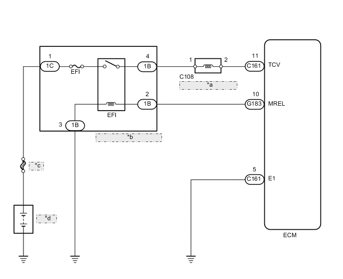
| *a | Timing Control Valve |
| *b | No. 1 Integration Relay |
| *c | P/I-B |
| *d | Battery |
CAUTION / NOTICE / HINT
Note
Inspect the fuses for circuits related to this system before performing the following inspection procedure.
Tech Tips
Read freeze frame data using the GTS. Freeze frame data records the engine condition when malfunctions are detected. When troubleshooting, freeze frame data can help determine if the vehicle was moving or stationary, if the engine was warmed up or not, and other data from the time the malfunction occurred.
PROCEDURE
-
INSPECT TIMING CONTROL VALVE
-
Inspect the timer control valve Click here.
NG 
REPLACE TIMING CONTROL VALVE
OK 
-
-
INSPECT TIMING CONTROL VALVE (POWER SOURCE)
-
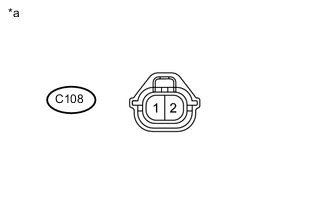
Text in Illustration *a Front view of wire harness connector
(to Timing Control Valve)
Disconnect the timing control valve connector.
-
Turn the ignition switch to ON.
-
Measure the voltage according to the value(s) in the table below.
Standard Voltage Tester Connection Switch Condition Specified Condition C108-1 - Body ground Ignition switch ON 11 to 14 V
NG
REPAIR OR REPLACE HARNESS OR CONNECTOR (TIMING CONTROL VALVE - NO. 1 INTEGRATION RELAY)
OK
-
-
CHECK HARNESS AND CONNECTOR (TIMING CONTROL VALVE - ECM)
-
Disconnect the timing control valve connector.
-
Disconnect the ECM connector.
-
Measure the resistance according to the value(s) in the table below.
Standard Resistance Tester Connection Condition Specified Condition C108-2 - C161-11 (TCV) Always Below 1 Ω C108-2 or C161-11 (TCV) - Body ground Always 10 kΩ or higher
NG
END
OK
-
-
CHECK FUEL FILTER ELEMENT SUB-ASSEMBLY
-
Check the fuel filter element sub-assembly.
NG
REPLACE FUEL FILTER ELEMENT SUB-ASSEMBLY Click here
OK
-
-
CHECK FUEL LEAK
-
Visually check the injection or supply pump assembly, each injector and fuel line for fuel leaks Click here.
OK No leakage
NG
REPAIR FUEL LEAK
OK
-
-
REPLACE INJECTION OR SUPPLY PUMP ASSEMBLY
-
Replace the injection or supply pump assembly Click here.
NEXT
-
-
CHECK READ OUTPUT DTC (DTC P1220 IS OUTPUT AGAIN)
-
Clear the DTC Click here.
-
Start the engine.
-
Idle the engine for 20 sec. or more.
-
Read the DTC Click here.
Result Display (DTC output) Proceed to DTC P1220 is output again A No DTC output B
A
REPLACE ECM Click here
B
END
-