СИСТЕМА ECD, Diagnostic DTC:P1222
| DTC Code | DTC Name |
|---|---|
| P1222 | Throttle Motor Circuit Range/Performance |
DESCRIPTION
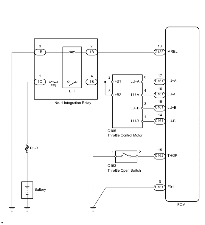
Throttle control motor is operated by the ECM and opens and closes the throttle valve.
The fully open position of the throttle valve is detected by the throttle open switch which is mounted on the venturi assembly.
If this DTC is stored, the ECM shuts down the power for the throttle control motor.
| DTC No. | DTC Detection Condition | Trouble Area |
|---|---|---|
| P1222 | Open or short in throttle control motor circuit. |
|
| Open or short in throttle open switch circuit. |
WIRING DIAGRAM
CAUTION / NOTICE / HINT
Note
Inspect the fuses for circuits related to this system before performing the following inspection procedure.
Tech Tips
Read freeze frame data using the GTS. Freeze frame data records the engine condition when malfunctions are detected. When troubleshooting, freeze frame data can help determine if the vehicle was moving or stationary, if the engine was warmed up or not, and other data from the time the malfunction occurred.
PROCEDURE
-
INSPECT THROTTLE OPEN SWITCH
-
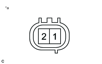
Text in Illustration *a Component without harness connected
(Throttle Open Switch)
Disconnect the throttle open switch connector.
-
Remove the venturi assembly.
-
Measure the resistance according to the value(s) in the table below.
Standard Resistance Tester Connection Condition Specified Condition 1 - 2 Throttle valve is opened Below 1 Ω 1 - 2 Throttle valve is closed 10 kΩ or higher Tech Tips
The throttle open switch is integrated with the venturi assembly. If the throttle open switch is replaced, the venturi assembly must be replaced in whole.
NG 
REPLACE VENTURI ASSEMBLY
OK 
-
-
CHECK HARNESS AND CONNECTOR (THROTTLE OPEN SWITCH - BODY GROUND, ECM - THROTTLE OPEN SWITCH)
-
Disconnect the throttle open switch connector.
-
Disconnect the ECM connector.
-
Measure the resistance according to the value(s) in the table below.
Standard Resistance Tester Connection Condition Specified Condition C163-2 - C162-15 (THOP) Always Below 1 Ω C163-1 - Body ground Always Below 1 Ω C163-2 or C162-15 (THOP) - Body ground Always 10 kΩ or higher
NG
REPAIR OR REPLACE HARNESS OR CONNECTOR
OK
-
-
CHECK TERMINAL VOLTAGE (THROTTLE CONTROL MOTOR)
-
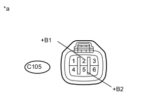
Text in Illustration *a Front view of wire harness connector
(to Throttle Control Motor)
Disconnect the throttle control motor connector.
-
Measure the voltage according to the value(s) in the table below.
Standard Voltage Tester Connection Switch Condition Specified Condition C105-2 (+B1) - Body ground Ignition switch ON 11 to 14 V C105-5 (+B2) - Body ground Ignition switch ON 11 to 14 V
NG
REPAIR OR REPLACE HARNESS OR CONNECTOR (THROTTLE CONTROL MOTOR - NO. 1 INTEGRATION RELAY)
OK
-
-
INSPECT THROTTLE CONTROL MOTOR
-
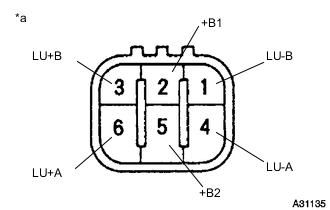
Text in Illustration *a Component without harness connected
(Throttle Control Motor)
Disconnect the throttle control motor connector.
-
Measure the resistance according to the value(s) in the table below.
Standard Resistance Tester Connection Condition Specified Condition 1 (LU-B) - 2 (+B1) 20°C (68°F) 18 to 22 Ω 2 (+B1) - 3 (LU+B) 20°C (68°F) 18 to 22 Ω 4 (LU-A) - 5 (+B2) 20°C (68°F) 18 to 22 Ω 5 (+B2) - 6 (LU+A) 20°C (68°F) 18 to 22 Ω Tech Tips
The throttle control motor is integrated with the venturi assembly. If the throttle control motor is replaced, the venturi assembly must be replaced in whole.
NG
REPLACE VENTURI ASSEMBLY
OK
-
-
CHECK HARNESS AND CONNECTOR (THROTTLE CONTROL MOTOR - ECM)
-
Disconnect the throttle control motor connector.
-
Disconnect the ECM connector.
-
Measure the resistance according to the value(s) in the table below.
Standard Resistance Tester Connection Condition Specified Condition C105-6 (LU+A) - C161-17 (LU+A) Always Below 1 Ω C105-4 (LU-A) - C161-16 (LU-A) Always Below 1 Ω C105-3 (LU+B) - C161-15 (LU+B) Always Below 1 Ω C105-1 (LU-B) - C161-14 (LU-B) Always Below 1 Ω C105-6 (LU+A) or C161-17 (LU+A) - Body ground Always 10 kΩ or higher C105-4 (LU-A) or C161-16 (LU-A) - Body ground Always 10 kΩ or higher C105-3 (LU+B) or C161-15 (LU+B) - Body ground Always 10 kΩ or higher C105-1 (LU-B) or C161-14 (LU-B) - Body ground Always 10 kΩ or higher
OK
REPLACE ECM Click here
NG
REPAIR OR REPLACE HARNESS OR CONNECTOR
-