OUTER MIRROR SWITCH INSPECTION
-
INSPECT OUTER MIRROR SWITCH ASSEMBLY (w/o Memory)
-
Check the mirror select switch and mirror surface adjust switch. (except TMMK Made)
-
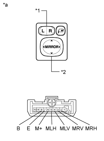
Text in Illustration *1 Mirror select switch *2 Mirror surface adjust switch *a Component without harness connected
(Outer Mirror Switch Assembly)
Turn the mirror select switch to the L position.
-
Measure the resistance according to the value(s) in the table below.
Standard Resistance (for left side) Tester Connection Condition Specified Condition 4 (MLV) - 8 (B)
6 (M+) - 7 (E)
UP Below 1 Ω OFF 10 kΩ or higher 4 (MLV) - 7 (E)
6 (M+) - 8 (B)
DOWN Below 1 Ω OFF 10 kΩ or higher 5 (MLH) - 8 (B)
6 (M+) - 7 (E)
LEFT Below 1 Ω OFF 10 kΩ or higher 5 (MLH) - 7 (E)
6 (M+) - 8 (B)
RIGHT Below 1 Ω OFF 10 kΩ or higher -
Turn the mirror select switch to the R position.
-
Measure the resistance according to the value(s) in the table below.
Standard Resistance (for right side) Tester Connection Condition Specified Condition 3 (MRV) - 8 (B)
6 (M+) - 7 (E)
UP Below 1 Ω OFF 10 kΩ or higher 3 (MRV) - 7 (E)
6 (M+) - 8 (B)
DOWN Below 1 Ω OFF 10 kΩ or higher 2 (MRH) - 8 (B)
6 (M+) - 7 (E)
LEFT Below 1 Ω OFF 10 kΩ or higher 2 (MRH) - 7 (E)
6 (M+) - 8 (B)
RIGHT Below 1 Ω OFF 10 kΩ or higher If the result is not as specified, replace the outer mirror switch assembly.
-
-
Check the mirror retract switch. (except TMMK Made)
-
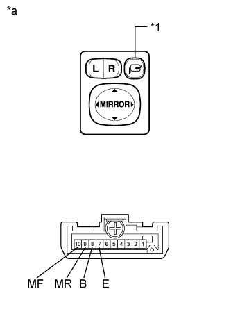
Text in Illustration *1 Mirror retract switch *a Component without harness connected
(Outer Mirror Switch Assembly)
Measure the resistance according to the value(s) in the table below.
Standard Resistance Tester Connection Condition Specified Condition 10 (MF) - 7 (E) Mirror retract switch retract position Below 1 Ω 9 (MR) - 8 (B) Below 1 Ω 10 (MF) - 8 (B) Mirror retract switch return position Below 1 Ω 9 (MR) - 7 (E) Below 1 Ω If the result is not as specified, replace the outer mirror switch assembly.
-
-
Check the mirror select switch and mirror surface adjust switch. (for TMMK Made)
-
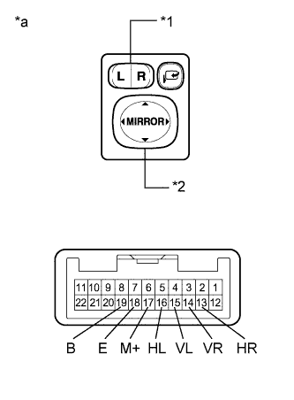
Turn the mirror select switch to the L position.
-
Measure the resistance according to the value(s) in the table below.
Standard Resistance (for left side) Tester Connection Switch Condition Specified Condition 15 (VL) - 19 (B)
17 (M+) - 18 (E)
UP Below 1 Ω OFF 10 kΩ or higher 15 (VL) - 18 (E)
17 (M+) - 19 (B)
DOWN Below 1 Ω OFF 10 kΩ or higher 16 (HL) - 19 (B)
17 (M+) - 18 (E)
LEFT Below 1 Ω OFF 10 kΩ or higher 16 (HL) - 18 (E)
17 (M+) - 19 (B)
RIGHT Below 1 Ω OFF 10 kΩ or higher -
Turn the mirror select switch to the R position.
-
Measure the resistance according to the value(s) in the table below.
Standard Resistance (for right side) Tester Connection Switch Condition Specified Condition 14 (VR) - 19 (B)
17 (M+) - 18 (E)
UP Below 1 Ω OFF 10 kΩ or higher 14 (VR) - 18 (E)
17 (M+) - 19 (B)
DOWN Below 1 Ω OFF 10 kΩ or higher 13 (HR) - 19 (B)
17 (M+) - 18 (E)
LEFT Below 1 Ω OFF 10 kΩ or higher 13 (HR) - 18 (E)
17 (M+) - 19 (B)
RIGHT Below 1 Ω OFF 10 kΩ or higher Text in Illustration *1 Mirror select switch *2 Mirror surface adjust switch *a Component without harness connected
(Outer Mirror Switch Assembly)
If the result is not as specified, replace the outer mirror switch assembly.
-
-
Check the mirror retract switch. (for TMMK Made)
-
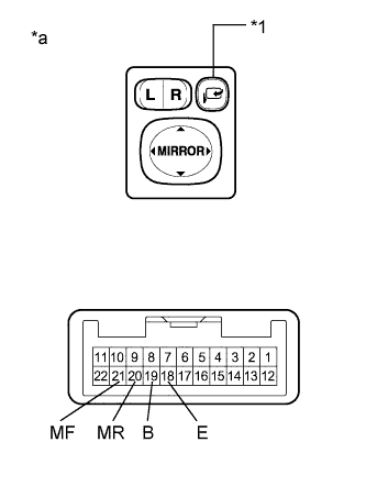
Measure the resistance according to the value(s) in the table below.
Standard Resistance Tester Connection Switch Condition Specified Condition 21 (MF) - 18 (E) Mirror retract switch retract position Below 1 Ω 20 (MR) - 19 (B) Below 1 Ω 21 (MF) - 19 (B) Mirror retract switch return position Below 1 Ω 20 (MR) - 18 (E) Below 1 Ω Text in Illustration *1 Mirror retract switch *a Component without harness connected
(Outer Mirror Switch Assembly)
If the result is not as specified, replace the outer mirror switch assembly.
-
-
-
INSPECT OUTER MIRROR SWITCH ASSEMBLY (w/ Memory)
-
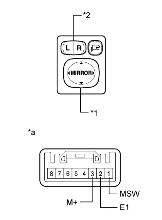
Text in Illustration *1 Mirror Adjust Switch *2 Mirror Select Switch *a Component without harness connected
(Outer Mirror Switch Assembly)
Check the switch functions.
-
Measure the resistance according to the value(s) in the table below.
Standard Resistance Tester Connection Condition Specified Condition 3 (M+) - 2 (E1) Mirror adjust switch pressed up 90 to 110 Ω Mirror adjust switch pressed down 437 to 503 Ω Mirror adjust switch pressed left 744 to 856 Ω Mirror adjust switch pressed right 225 to 275 Ω Mirror adjust switch not pressed 10 kΩ or higher 1 (MSW) - 2 (E1) Mirror select switch R Below 1 Ω Mirror select switch L 90 to 110 Ω Mirror select switch off 10 kΩ or higher If the result is not as specified, replace the outer mirror switch assembly.
-
-
Check the mirror retract switch.
-
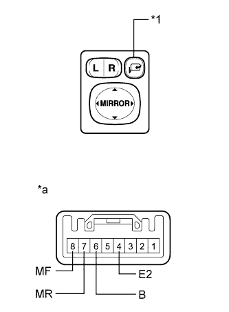
Text in Illustration *1 Mirror retract switch *a Component without harness connected
(Outer Mirror Switch Assembly)
Measure the resistance according to the value(s) in the table below.
Standard Resistance Tester Connection Condition Specified Condition 8 (MF) - 4 (E2) Mirror retract switch retract position Below 1 Ω 7 (MR) - 6 (B) Below 1 Ω 8 (MF) - 6 (B) Mirror retract switch return position Below 1 Ω 7 (MR) - 4 (E2) Below 1 Ω 7 (MR) - 8 (MF) Always 10 kΩ or higher If the result is not as specified, replace the outer mirror switch assembly.
-
-