POWER MIRROR CONTROL SYSTEM (w/ Memory) Driver Side Power Mirror cannot be Adjusted with Power Mirror Switch
SYSTEM DESCRIPTION
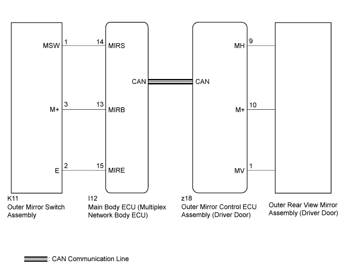
When the mirror adjust switch is operated, the main body ECU (multiplex network body ECU) detects the switch operation and sends the mirror adjust switch signal to the outer mirror control ECU assembly (driver door) via CAN communication. On receiving the signal, the outer mirror control ECU assembly (driver door) operates the vertical and horizontal mirror motors, which are built into the outer rear view mirror assembly (driver door), to adjust the mirror surface position.
WIRING DIAGRAM
INSPECTION PROCEDURE
Note
The power mirror control system (w/ Memory) uses the CAN communication system. Inspect the communication function by following How to Proceed with Troubleshooting. Troubleshoot the power mirror control system (w/ Memory) after confirming that the communication systems are functioning properly Click here.
PROCEDURE
-
READ VALUE USING GTS
-
Connect the GTS to the DLC3.
-
Turn the engine switch on (IG).
-
Turn the GTS on.
-
Enter the following menus: Body Electrical / Main Body / Data List.
-
Read the Data List according to the display on the GTS.
Main Body Tester Display Measurement Item/Range Normal Condition Diagnostic Note Mirror Selection SW (L) Mirror select switch signal for LH mirror / ON or OFF ON: Mirror select switch in L position
OFF: Mirror select switch off or in R position
- Mirror Position SW (R) Mirror adjust switch signal (Right) / ON or OFF ON: Mirror adjust switch pressed right
OFF: Mirror adjust switch not pressed right
Check with the mirror select switch in the L position. Mirror Position SW (L) Mirror adjust switch signal (Left) / ON or OFF ON: Mirror adjust switch pressed left
OFF: Mirror adjust switch not pressed left
Check with the mirror select switch in the L position. Mirror Position SW (Up) Mirror adjust switch signal (Up) / ON or OFF ON: Mirror adjust switch pressed up
OFF: Mirror adjust switch not pressed up
Check with the mirror select switch in the L position. Mirror Position SW (Dwn) Mirror adjust switch signal (Down) / ON or OFF ON: Mirror adjust switch pressed down
OFF: Mirror adjust switch not pressed down
Check with the mirror select switch in the L position. OK On the GTS screen, ON or OFF is displayed accordingly.
NG 
INSPECT OUTER MIRROR SWITCH ASSEMBLY Click here
OK 
-
-
PERFORM ACTIVE TEST USING GTS
-
Enter the following menus: Body Electrical / Mirror L / Active Test.
-
Perform the Active Test according to the display on the GTS.
Mirror L / Mirror R Tester Display Test Part Control Range Diagnostic Note Mirror Up/Down Mirror vertical operation Up / Down
-
Operate with engine switch on (IG) and the vehicle stopped.
-
This test tilts the mirror up or down.
-
This operation can be confirmed by watching the mirror move in the desired direction.
Mirror Right/Left Mirror horizontal operation Right / Left
-
Operate with engine switch on (IG) and the vehicle stopped.
-
This test tilts the mirror right or left
-
This operation can be confirmed by watching the mirror move in the desired direction.
OK Power mirror operation is normal. -
NG
INSPECT OUTER REAR VIEW MIRROR ASSEMBLY (DRIVER DOOR) Click here
OK 
REPLACE OUTER MIRROR CONTROL ECU ASSEMBLY (DRIVER DOOR) Click here
-
-
INSPECT OUTER REAR VIEW MIRROR ASSEMBLY (DRIVER DOOR)
-
Remove the outer rear view mirror assembly (driver door) Click here.
-
Inspect the outer rear view mirror assembly (driver door) (mirror surface) Click here.
NG 
REPLACE OUTER REAR VIEW MIRROR ASSEMBLY (DRIVER DOOR) Click here
OK
REPLACE OUTER MIRROR CONTROL ECU ASSEMBLY (DRIVER DOOR) Click here
-
-
INSPECT OUTER MIRROR SWITCH ASSEMBLY
-
Remove the outer mirror switch assembly Click here.
-
Inspect the outer mirror switch assembly Click here.
NG
REPLACE OUTER MIRROR SWITCH ASSEMBLY Click here
OK
-
-
CHECK HARNESS AND CONNECTOR (OUTER MIRROR SWITCH - MAIN BODY ECU)
-
Disconnect the K11 connector from the outer mirror switch assembly.
-
Disconnect the I12 connector from the main body ECU (multiplex network body ECU).
-
Measure the resistance according to the value(s) in the table below.
Standard Resistance Tester Connection Condition Specified Condition K11-2 (E) - I12-15 (MIRE) Always Below 1 Ω K11-3 (M+) - I12-13 (MIRB) Always Below 1 Ω K11-1 (MSW) - I12-14 (MIRS) Always Below 1 Ω K11-2 (E) - Body ground Always 10 kΩ or higher K11-3 (M+) - Body ground Always 10 kΩ or higher K11-1 (MSW) - Body ground Always 10 kΩ or higher
NG
REPAIR OR REPLACE HARNESS OR CONNECTOR
OK
REPLACE MAIN BODY ECU (MULTIPLEX NETWORK BODY ECU) Click here
-