FUEL LID LOCK CONTROL CABLE ASSEMBLY (for TMMK Made LHD) INSTALLATION
-
INSTALL FUEL LID LOCK CONTROL CABLE SUB-ASSEMBLY
-
Install the fuel lid lock control cable sub-assembly to the luggage door lock control cable sub-assembly with a new clamp and the 3 pieces of tape as shown in the illustration.
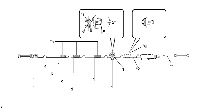
Text in Illustration *1 Luggage Door Lock Control Cable Sub-assembly *2 Fuel Lid Lock Control Cable Sub-assembly *a Clamp (A) *b Clamp *c Tape - - Reference Measurement Area Measurement Area Measurement a 295 to 305 mm (11.6 to 12.0 in.) b 880 to 900 mm (2.29 to 2.95 ft.) c 2090 to 2110 mm (6.86 to 6.92 ft.) d 2970 to 2990 mm (8.86 to 9.81 ft.) e 5.0 mm (0.197 in.) or less - - Note
-
Wrap tape around the designated position 1 to 3 times.
-
Make sure that the fuel lid lock control cable sub-assembly and luggage door lock control cable sub-assembly are not kinked.
-
-
Engage the 10 clamps and install the fuel lid lock control cable sub-assembly and luggage door lock control cable sub-assembly.
-
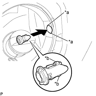
Text in Illustration *a Cutout *b Guide Align the cutouts and guides, and then insert the fuel filler opening lid lock retainer.
-
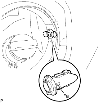
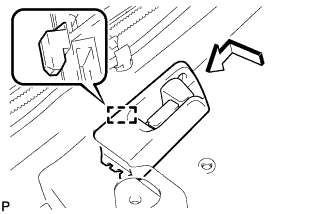
Text in Illustration *a Claw Engage the 2 claws and install the fuel filler opening lid lock retainer.
-
Engage the 2 claws and install the fuel lid lock control cable sub-assembly.
-
Engage the clamp and connect the luggage door lock control cable sub-assembly.
-
Connect the luggage door lock control cable sub-assembly.
-
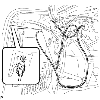
Engage the guide as shown in the illustration.
-
Return the floor carpet to the original position.
-
Engage the 2 clamps and install the 2 scuff plate clips.
-
Engage the 3 clamps and connect the wire harness.
-
-
INSTALL FUEL LID LOCK OPEN LEVER SUB-ASSEMBLY
-
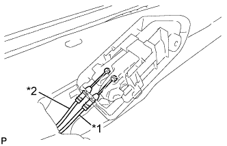
Text in Illustration *1 Luggage Door Lock Control Cable Sub-assembly *2 Fuel Lid Lock Control Cable Sub-assembly Connect the fuel lid lock control cable sub-assembly and luggage door lock control cable sub-assembly to the fuel lid lock open lever sub-assembly.
-
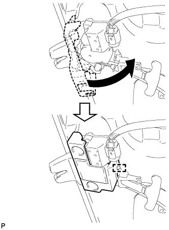
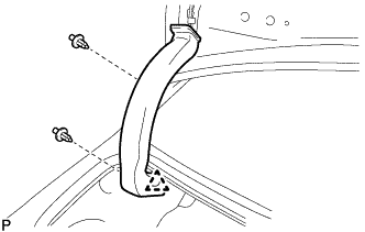
Engage the guide and install the fuel lid lock open lever sub-assembly as shown in the illustration.
-
Install the screw.
-
-
INSTALL LUGGAGE COMPARTMENT INNER TRIM COVER LH
-
Engage the fastener.
-
Install the luggage compartment inner trim cover LH with the 2 clips.
-
-
INSTALL NO. 1 LUGGAGE COMPARTMENT TRIM HOOK
-
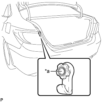
Text in Illustration *a Pin Engage the pin to install the No. 1 luggage compartment trim hook.
-
-
INSTALL REAR FLOOR FINISH PLATE
-
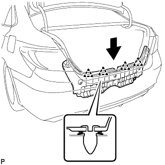
Engage the 4 clips to install the rear floor finish plate as shown in the illustration.
-
Install the 5 clips.
-
-
INSTALL SPARE WHEEL COVER ASSEMBLY
-
Install the spare wheel cover assembly.
-
-
INSTALL LUGGAGE COMPARTMENT DOOR HINGE COVER LH
-
Engage the clip.
-
Install the luggage compartment door hinge cover LH with the 2 clips.
-
-
INSTALL LUGGAGE COMPARTMENT DOOR COVER
-
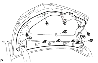
Install the luggage compartment door cover with the 13 clips.
-
-
INSTALL CENTER PILLAR LOWER GARNISH LH
-
Engage the 2 claws and 3 clips to install the center pillar lower garnish LH.
-
-
CONNECT FRONT SEAT OUTER BELT ASSEMBLY LH
-
Install the floor anchor of the front seat outer belt assembly with the bolt.
- Torque:
- 42 N*m { 428 kgf*cm, 31 ft.*lbf }
-
Check if the ELR locks.
Note
The check should be performed with the front seat outer belt assembly installed.
-
With the belt assembly installed, check that the belt locks when it is pulled out quickly.
-
-
-
INSTALL LAP BELT OUTER ANCHOR COVER
-
Engage the 3 claws to install the lap belt outer anchor cover.
-
-
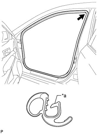
INSTALL REAR DOOR OPENING TRIM WEATHERSTRIP LH
-
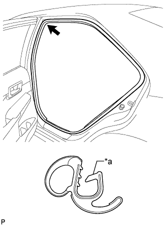
Text in Illustration *a Alignment Mark (Pink) Align the alignment mark (Pink) on the weatherstrip with the protruding portion on the vehicle body indicated by the arrow in the illustration, and install the rear door opening trim weatherstrip LH.
Note
After installation, check that the corners fit correctly.
-
-
INSTALL REAR DOOR SCUFF PLATE LH
-
Engage the 6 claws to install the rear door scuff plate LH.
Tech Tips
Engage the claws from the rear side of the scuff plate.
-
-
INSTALL FRONT DOOR OPENING TRIM WEATHERSTRIP LH
-
Text in Illustration *a Alignment Mark (Yellow) Align the alignment mark (Yellow) on the weatherstrip with the protruding portion on the vehicle body indicated by the arrow in the illustration, and install the front door opening trim weatherstrip LH.
Note
After installation, check that the corners fit correctly.
-
-
INSTALL FRONT DOOR SCUFF PLATE LH
-
Engage the 10 claws to install the front door scuff plate LH.
-
-
INSTALL REAR SIDE SEATBACK ASSEMBLY LH
-
Engage the hook.
-
Install the rear side seatback assembly LH with the 2 bolts.
- Torque:
- 18 N*m { 184 kgf*cm, 13 ft.*lbf }
-
Connect the connector.
-
Connect the rear seat outer belt assembly to the rear seat shoulder belt guide.
-
-
INSTALL REAR SEAT CUSHION LOCK HOOK
-
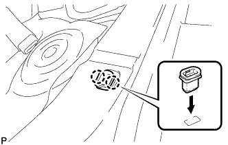
Engage the 2 claws to install a new rear seat cushion lock hook as shown in the illustration.
Note
Rear seat cushion lock hooks must not be reused.
Tech Tips
Use the same procedure for the RH side and the LH side.
-
-
INSTALL REAR SEAT CUSHION ASSEMBLY
-
Place the rear seat cushion assembly in the cabin.
Note
Be careful not to damage the vehicle body.
-
Pass the 2 rear seat inner belt assemblies through the rear seat cushion assembly.
-
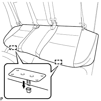
Engage the 2 rear seat cushion frame hooks on the front side of the rear seat cushion assembly to the 2 rear seat cushion lock hooks as shown in the illustration.
-
Confirm that the rear seat cushion assembly is securely installed.
Note
When installing the rear seat cushion assembly, make sure that the seat belt buckles are not under the rear seat cushion assembly.
-
-
INSTALL FRONT SEAT ASSEMBLY LH (for Manual Seat)
-
INSTALL FRONT SEAT ASSEMBLY LH (for Power Seat)
-
CONNECT CABLE TO NEGATIVE BATTERY TERMINAL
Note
When disconnecting the cable, some systems need to be initialized after the cable is reconnected Click here.
-
INSPECT SRS WARNING LIGHT