LUGGAGE COMPARTMENT DOOR (for TMMK Made) ADJUSTMENT
-
REMOVE LUGGAGE COMPARTMENT DOOR COVER
-
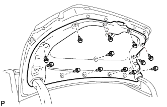
Remove the 13 clips and luggage compartment door cover.
-
-
REMOVE SPARE WHEEL COVER ASSEMBLY
-
Remove the spare wheel cover assembly.
-
-
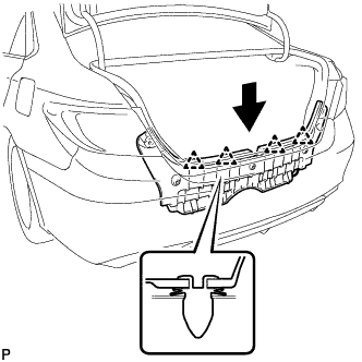
REMOVE REAR FLOOR FINISH PLATE
-
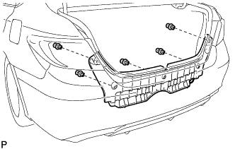
Remove the 5 clips.
-
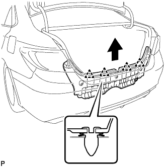
Disengage the 4 clips and remove the rear floor finish plate as shown in the illustration.
-
-
REMOVE LUGGAGE COMPARTMENT DOOR HINGE COVER LH
-
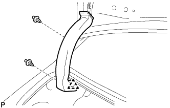
Remove the 2 clips.
-
Disengage the clip and remove the luggage compartment door hinge cover LH.
-
-
REMOVE LUGGAGE COMPARTMENT DOOR HINGE COVER RH
Tech Tips
Use the same procedure as for the LH side.
-
ADJUST LUGGAGE COMPARTMENT DOOR
-
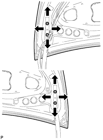
Loosen the door side hinge bolts to adjust the door horizontally and vertically.
- Torque:
- 7.5 N*m { 77 kgf*cm, 66 in.*lbf }
-

Using a T40 "TORX" socket wrench, slightly loosen the striker mounting screws.
-
Using a brass bar and a hammer, hit the striker to adjust its position.
-
Using a T40 "TORX" socket wrench, tighten the striker mounting screws after adjustment.
- Torque:
- 23 N*m { 235 kgf*cm, 17 ft.*lbf }
-
-
INSTALL LUGGAGE COMPARTMENT DOOR HINGE COVER LH
-
Engage the clip.
-
Install the luggage compartment door hinge cover LH with the 2 clips.
-
-
INSTALL LUGGAGE COMPARTMENT DOOR HINGE COVER RH
Tech Tips
Use the same procedure as for the LH side.
-
INSTALL REAR FLOOR FINISH PLATE
-
Engage the 4 clips to install the rear floor finish plate as shown in the illustration.
-
Install the 5 clips.
-
-
INSTALL SPARE WHEEL COVER ASSEMBLY
-
Install the spare wheel cover assembly.
-
-
INSTALL LUGGAGE COMPARTMENT DOOR COVER
-
Install the luggage compartment door cover with the 13 clips.
-
-
INSPECT LUGGAGE COMPARTMENT DOOR
-
Check that the clearance measurements of areas a through d are within each standard range.
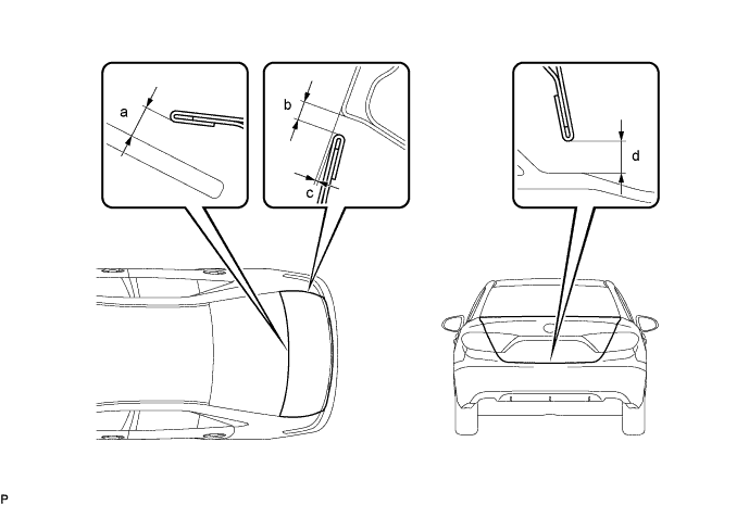
Standard Clearance Area Measurement Area Measurement a 6.15 mm (0.242 in.) b 2.0 to 5.0 mm (0.0787 to 0.197 in.) c -1.2 to 1.8 mm (-0.0472 to 0.0709 in.) d 6.05 mm (0.238 in.)
-