REAR DOOR (for TMMK Made) ADJUSTMENT

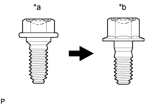
| *a | Centering Bolt |
| *b | Standard Bolt |
Tech Tips
-
Use the same procedure for the RH side and LH side.
-
The following procedure is for the LH side.
-
Centering bolts are used to mount the door hinge to the vehicle body and door. The door cannot be adjusted with the centering bolts installed. Substitute the centering bolts with standard bolts when making adjustments.
-
Specified torque for standard bolts is shown in the standard bolt chart Click here.
-
INSPECT REAR DOOR
-
Check that the clearance measurements of areas a through r are within each standard range.
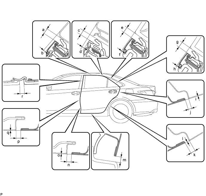
Standard Clearance Area Measurement Area Measurement a 3.35 to 6.35 mm (0.132 to 0.250 in.) b 0.5 to 3.5 mm (0.0197 to 0.138 in.) c 4.1 to 7.1 mm (0.161 to 0.280 in.) d 0.9 to 3.9 mm (0.0354 to 0.154 in.) e 4.3 to 7.3 mm (0.169 to 0.287 in.) f -1.4 to 1.6 mm (-0.0551 to 0.0630 in.) g 4.3 to 7.3 mm (0.169 to 0.287 in.) h -1.0 to 2.0 mm (-0.0394 to 0.0787 in.) i -1.5 to 1.5 mm (-0.0591 to 0.0591 in.) j 2.7 to 5.7 mm (0.106 to 0.224 in.) k 2.7 to 5.7 mm (0.106 to 0.224 in.) l -1.5 to 1.5 mm (-0.0591 to 0.0591 in.) m 3.05 to 7.25 mm (0.120 to 0.285 in.) n 2.96 to 4.64 mm (0.117 to 0.183 in.) o -0.84 to 0.84 mm (-0.0331 to 0.0331 in.) p 2.96 to 4.64 mm (0.117 to 0.183 in.) q -0.84 to 0.84 mm (-0.0331 to 0.0331 in.) r 2.3 to 6.3 mm (0.0906 to 0.248 in.)
-
-
ADJUST REAR DOOR
Note
Make sure that the turn the engine switch off when adjusting door lock strikers.
-
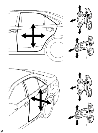
Using SST, loosen the hinge bolts on the vehicle body and adjust the door position.
- SST
- 09812-00010
-
Tighten the hinge bolts on the vehicle body after the adjustment.
- Torque:
- 26 N*m { 265 kgf*cm, 19 ft.*lbf }
-
Loosen the hinge bolts on the door and adjust the door position.
-
Tighten the hinge bolts on the door after the adjustment.
- Torque:
- 26 N*m { 265 kgf*cm, 19 ft.*lbf }
-
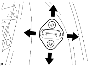
Using a T40 "TORX" socket wrench, slightly loosen the striker mounting screws.
-
Using a brass bar and a hammer, hit the striker to adjust its position.
-
Using a T40 "TORX" socket wrench, tighten the striker mounting screws after adjustment.
- Torque:
- 23 N*m { 235 kgf*cm, 17 ft.*lbf }
-