LUGGAGE COMPARTMENT DOOR (for TMC, TMMR Made) ADJUSTMENT
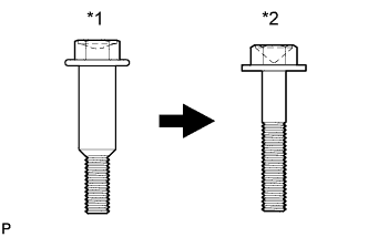
| *1 | Centering Bolt |
| *1 | Standard Bolt |
Tech Tips
-
Centering bolts are used to mount the door hinge to the door. The door cannot be adjusted with the centering bolts installed. Substitute the centering bolts with standard bolts when making adjustments.
-
Specified torque for standard bolts is shown in the standard bolt chart Click here.
-
REMOVE LUGGAGE COMPARTMENT DOOR COVER
-
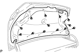
Remove the 13 clips and luggage compartment door cover.
-
-
REMOVE LUGGAGE COMPARTMENT FLOOR MAT
-
Remove the luggage compartment floor mat.
-
-
REMOVE BAGGAGE HOLDER NET (w/ Partition Net)
-
Remove the baggage holder net.
-
-
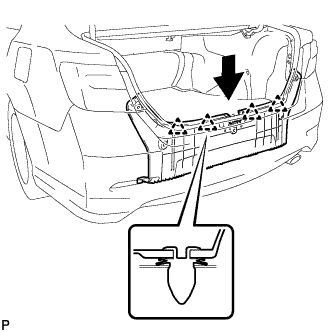
REMOVE REAR FLOOR FINISH PLATE
-
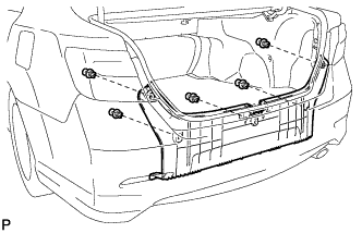
Remove the 5 clips.
-
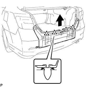
Disengage the 4 clips and remove the rear floor finish plate.
-
-
ADJUST LUGGAGE COMPARTMENT DOOR
-
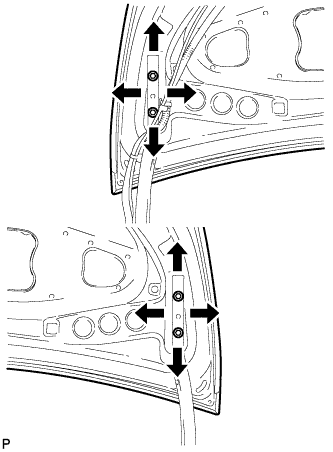
Loosen the door side hinge bolts to adjust the door horizontally and vertically.
- Torque:
- 7.5 N*m { 77 kgf*cm, 66 in.*lbf }
-

Using a T40 "TORX" socket wrench, slightly loosen the striker mounting screws.
-
Using a brass bar and a hammer, hit the striker to adjust its position.
-
Using a T40 "TORX" socket wrench, tighten the striker mounting screws after adjustment.
- Torque:
- 23 N*m { 235 kgf*cm, 17 ft.*lbf }
-
-
INSTALL REAR FLOOR FINISH PLATE
-
Engage the 4 clips and install the rear floor finish plate.
-
Install the 5 clips.
-
-
INSTALL BAGGAGE HOLDER NET (w/ Partition Net)
-
Install the baggage holder net.
-
-
INSTALL LUGGAGE COMPARTMENT FLOOR MAT
-
Install the luggage compartment floor mat.
-
-
INSTALL LUGGAGE COMPARTMENT DOOR COVER
-
Install the luggage compartment door cover with the 13 clips.
-
-
INSPECT LUGGAGE COMPARTMENT DOOR PANEL SUB-ASSEMBLY
-
Check that the clearance measurements of areas *a through *d are within each standard range.
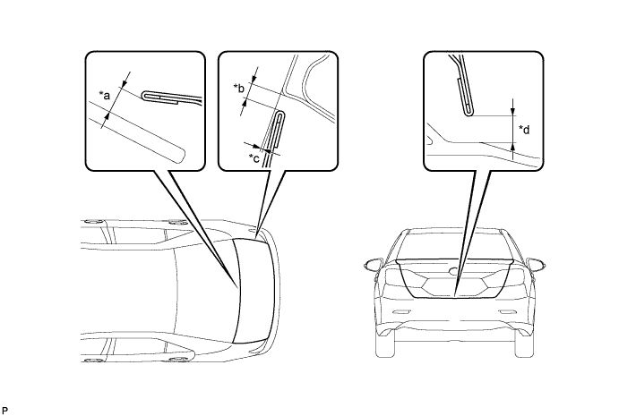
Standard Clearance Area Measurement Area Measurement *a 6.4 mm (0.252 in.) *b 2.0 to 5.0 mm (0.0787 to 0.197 in.) *c -1.5 to 1.5 mm (-0.0591 to 0.0591 in.) *d 3.7 to 7.7 mm (0.146 to 0.303 in.)
-