SLIDING ROOF SYSTEM, Diagnostic DTC:B2342
| DTC Code | DTC Name |
|---|---|
| B2342 | Switch Failure |
DESCRIPTION
This DTC is stored when the sliding roof ECU (sliding roof drive gear sub-assembly) detects that the sliding roof switch is stuck for 30 seconds or more.
| DTC No. | DTC Detection Condition | Trouble Area |
|---|---|---|
| B2342 | Sliding roof ECU (sliding roof drive gear sub-assembly) detects sliding roof switch is stuck for 30 seconds or more. |
|
WIRING DIAGRAM
Refer to DTC B2341 Click here.
INSPECTION PROCEDURE
Note
When the sliding roof ECU (sliding roof drive gear sub-assembly) is removed and reinstalled or replaced, it requires initialization Click here.
PROCEDURE
-
READ VALUE USING INTELLIGENT TESTER (SLIDING ROOF SWITCH)
-
Connect the intelligent tester to the DLC3.
-
Turn the ignition switch to ON.
-
Turn the intelligent tester on.
-
Enter the following menus: Body / Sliding Roof / Data List.
-
Read the Data List according to the display on the intelligent tester.
Sliding Roof (Sliding Roof ECU (Sliding Roof Drive Gear Sub-assembly)) Tester Display Measurement Item/Range Normal Condition Diagnostic Note Open Switch Failure(Past) Open switch failure signal (Past)/ON or OFF ON: Sliding roof open switch failure signal (Past)
OFF: No sliding roof open switch failure signal (Past)
- Close Switch Failure(Past) Close switch failure signal (Past)/ON or OFF ON: Sliding roof close switch failure signal (Past)
OFF: No sliding roof close switch failure signal (Past)
- Up Switch Failure(Past) Up switch failure signal (Past)/ON or OFF ON: Sliding roof tilt up switch failure signal (Past)
OFF: No sliding roof tilt up switch failure signal (Past)
- Down Switch Failure(Past) Down switch failure signal (Past)/ON or OFF ON: Sliding roof tilt down switch failure signal (Past)
OFF: No sliding roof tilt down switch failure signal (Past)
- Open Switch Failure(Current) Open switch failure signal (Current)/ON or OFF ON: Sliding roof open switch failure signal (Current)
OFF: No sliding roof open switch failure signal (Current)
- Close Switch Failure(Current) Close switch failure signal (Current)/ON or OFF ON: Sliding roof close switch failure signal (Current)
OFF: No sliding roof close switch failure signal (Current)
- Up Switch Failure(Current) Up switch failure signal (Current)/ON or OFF ON: Sliding roof tilt up switch failure signal (Current)
OFF: No sliding roof tilt up switch failure signal (Current)
- Down Switch Failure(Current) Down switch failure signal (Current)/ON or OFF ON: Sliding roof tilt down switch failure signal (Current)
OFF: No sliding roof tilt down switch failure signal (Current)
- OK "OFF" appears on the intelligent tester screen.
NG 
CHECK HARNESS AND CONNECTOR (SLIDING ROOF ECU - BODY GROUND) Click here
OK 
REPLACE SLIDING ROOF ECU (SLIDING ROOF DRIVE GEAR SUB-ASSEMBLY) Click here
-
-
CHECK HARNESS AND CONNECTOR (SLIDING ROOF ECU - BODY GROUND)
-
Disconnect the S4 sliding roof ECU (sliding roof drive gear sub-assembly) connector.
-
Disconnect the S7*1 or S14*2 sliding roof switch (roof console box assembly) connector.
-
*1: except TMMK Made
*2: for TMMK Made
-
-
Measure the resistance according to the value(s) in the table below.
Standard Resistance Tester Connection Condition Specified Condition S4-7 (OPN) - Body ground Always 10 kΩ or higher S4-6 (DWN) - Body ground Always 10 kΩ or higher S4-5 (CLS) - Body ground Always 10 kΩ or higher S4-4 (UP) - Body ground Always 10 kΩ or higher
NG 
REPAIR OR REPLACE HARNESS OR CONNECTOR
OK 
-
-
INSPECT SLIDING ROOF SWITCH (ROOF CONSOLE BOX ASSEMBLY)
-
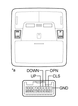
Text in Illustration *a Component without harness connected
(Sliding Roof Switch (Roof Console Box Assembly))
Remove the sliding roof switch (roof console box assembly) Click here.
-
Measure the resistance according to the value(s) in the table below.
Standard Resistance Tester Connection Switch Condition Specified Condition 5 (UP) - 1 (GND) UP switch is pressed Below 1 Ω 5 (UP) - 1 (GND) UP switch is not pressed 10 kΩ or higher 4 (DOWN) - 1 (GND) DOWN switch is pressed Below 1 Ω 4 (DOWN) - 1 (GND) DOWN switch is not pressed 10 kΩ or higher 3 (OPN) - 1 (GND) OPEN switch is pressed Below 1 Ω 3 (OPN) - 1 (GND) OPEN switch is not pressed 10 kΩ or higher 2 (CLS) - 1 (GND) CLOSE switch is pressed Below 1 Ω 2 (CLS) - 1 (GND) CLOSE switch is not pressed 10 kΩ or higher
NG
REPLACE SLIDING ROOF SWITCH (ROOF CONSOLE BOX ASSEMBLY) Click here
OK
REPLACE SLIDING ROOF ECU (SLIDING ROOF DRIVE GEAR SUB-ASSEMBLY) Click here
-