BACK WINDOW GLASS (for TMMK Made) INSTALLATION
-
INSTALL NO. 2 BACK WINDOW GLASS STOPPER (for 2-piece Type)
-
Using a brush or sponge, coat the installation area of 2 new No. 2 back window glass stoppers with primer G.
Note
-
Do not apply too much primer G.
-
Allow the primer G to dry for 3 minutes or more.
-
Throw away any leftover primer G.
Tech Tips
If an area other than specified is coated by accident, wipe off the primer G with a clean piece of cloth before it dries.
-
-
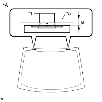
Text in Illustration *A Back Side *1 Ceramic Notch *a Back Window Glass Edge Install the 2 new No. 2 back window glass stoppers to the back window glass as shown in the illustration.
Standard Dimension Area Dimension a 14.2 to 15.2 mm (0.559 to 0.598 in.) Tech Tips
Only 2-piece type back window glass stoppers are provided as supply parts. Use 2-piece type stoppers as replacements even if 1-piece type stoppers were originally installed.
-
-
INSTALL NO. 1 BACK WINDOW GLASS STOPPER (for 2-piece Type)
-
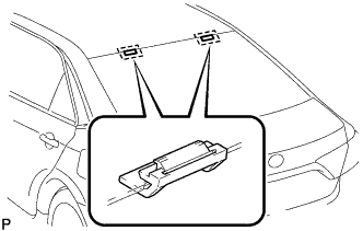
Install 2 new No. 1 back window glass stoppers to the vehicle body as shown in the illustration.
Tech Tips
Only 2-piece type back window glass stoppers are provided as supply parts. Use 2-piece type stoppers as replacements even if 1-piece type stoppers were originally installed.
-
-
INSTALL BACK WINDOW OUTSIDE MOULDING
-
Using a brush or sponge, coat the installation area of a new back window outside moulding with primer G.
Note
-
Do not apply too much primer G.
-
Allow the primer G to dry for 3 minutes or more.
-
Throw away any leftover primer G.
Tech Tips
If an area other than specified is coated by accident, wipe off the primer G with a clean piece of cloth before it dries.
-
-
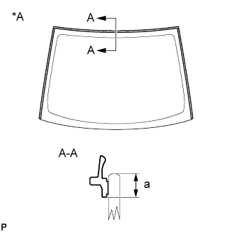
Text in Illustration *A Back Side Install the new back window outside moulding to the back window glass as shown in the illustration.
Standard Dimension Area Dimension a 7.4 mm (0.291 in.)
-
-
INSTALL BACK WINDOW GLASS ADHESIVE DAM
-
Using a brush or sponge, coat the installation area of a new back window glass adhesive dam with primer G.
Note
-
Do not apply too much primer G.
-
Allow the primer G to dry for 3 minutes or more.
-
Throw away any leftover primer G.
Tech Tips
If an area other than specified is coated by accident, wipe off the primer G with a clean piece of cloth before it dries.
-
-
Install the new back window glass adhesive dam to the back window glass as shown in the illustration.
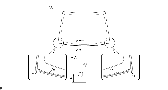
Text in Illustration *A Back Side - - *1 Ceramic Notch - - *a Adhesive Center Line - - Standard Dimension Area Dimension a 10.0 mm (0.394 in.)
-
-
INSTALL BACK WINDOW GLASS SUB-ASSEMBLY
-
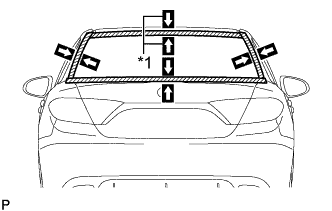
Text in Illustration *1 Matchmark Position the back window glass sub-assembly.
-
Using suction cups, place the back window glass sub-assembly in the correct position.
-
Check that the whole contact surface of the back window glass sub-assembly is perfectly even.
-
Align the matchmarks on the back window glass sub-assembly and vehicle body.
Note
Check that the back window glass stoppers are engaged to the vehicle body correctly.
-
Remove the back window glass sub-assembly.
-
-
Using a brush, coat the installation surface on the vehicle body with primer M.
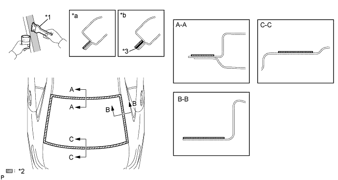
Text in Illustration *1 Brush *2 Primer M *3 Adhesive - - *a Correct *b Incorrect Note
-
Do not coat the adhesive with primer M.
-
Do not apply too much primer M.
-
Allow the primer M to dry for 3 minutes or more.
-
Throw away any leftover primer M.
Tech Tips
If an area other than specified is coated by accident, wipe off the primer M with a clean piece of cloth before it dries.
-
-
Using a brush or sponge, coat the adhesive application area with primer G.
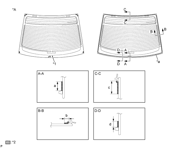
Text in Illustration *A Back Side - - *1 Ceramic Notch *2 Primer G *a Adhesive Center Line - - Standard Dimension Area Dimension a 18.5 mm (0.728 in.) or more b 14.0 mm (0.551 in.) or more c 14.0 mm (0.551 in.) or more d 11.0 mm (0.433 in.) or more Note
-
Do not apply too much primer G.
-
Allow the primer G to dry for 3 minutes or more.
-
Throw away any leftover primer G.
Tech Tips
If an area other than specified is coated by accident, wipe off the primer G with a clean piece of cloth before it dries.
-
-
Apply adhesive to the back window glass sub-assembly.
Adhesive Toyota Genuine Windshield Glass Adhesive or equivalent
-
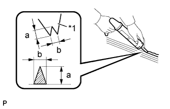
Text in Illustration *1 Nozzle Cut off the tip of the cartridge nozzle as shown in the illustration.
Standard Dimension Area Dimension a 12.0 mm (0.472 in.) b 8.0 mm (0.315 in.) -
Load the sealer gun with the cartridge.
-
Apply adhesive to the back window glass sub-assembly as shown in the illustration.
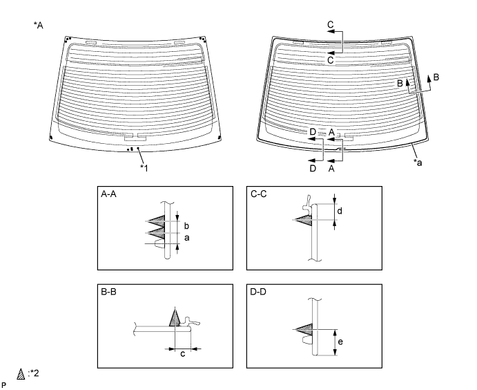
Text in Illustration *A Back Side - - *1 Ceramic Notch *2 Adhesive *a Adhesive Center Line - - Standard Dimension Area Dimension a 6.5 mm (0.256 in.) b 8.0 mm (0.315 in.) c 10.0 mm (0.394 in.) d 10.0 mm (0.394 in.) e 16.5 mm (0.650 in.) Tech Tips
Apply adhesive to the ceramic notches.
-
-
Install the back window glass sub-assembly.
-
Text in Illustration *1 Matchmark Using suction cups, position the back window glass sub-assembly so that the matchmarks are aligned, and press it in gently along the rim.
Note
-
Check that the back window glass stoppers are engaged to the vehicle body correctly.
-
Check the clearance between the vehicle body and back window glass sub-assembly.
-
-
Lightly press the front surface of the back window glass sub-assembly to ensure that the back window glass sub-assembly is securely fit to the vehicle body.
Tech Tips
Press the glass with a force of 98 N (10 kgf, 22.0 lbf) or more.
-
Using a scraper, remove any excess or protruding adhesive.
-
Hold the back window glass sub-assembly using protective tape until the applied adhesive becomes hard.
Note
Do not drive the vehicle for the time described in the table below.
Minimum Time Temperature Minimum Time Prior to Driving Vehicle 35°C (95°F) 1 hour and 30 minutes 20°C (68°F) 5 hours 5°C (41°F) 24 hours
-
-
Connect each connector.
-
-
INSPECT FOR LEAK
-
After the adhesive has hardened, apply water from the outside of the vehicle. Check that no water leaks into the cabin.
-
If water leaks into the cabin, allow the water to dry and add adhesive.
-
Remove the protective tape.
-
-
INSTALL PACKAGE TRAY TRIM PANEL ASSEMBLY
-
Pass the 3 rear seat belt floor anchors through the package tray trim panel assembly.
-
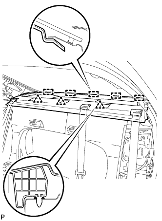
Engage the 5 guides and 3 clips to install the package tray trim panel assembly.
-
-
INSTALL REAR SEAT SHOULDER BELT COVER
-
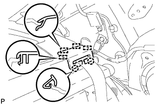
Engage the 4 guides and 2 claws to install the rear seat shoulder belt cover.
Tech Tips
Use the same procedure for the other 2 rear seat shoulder belt covers.
-
-
INSTALL CHILD RESTRAINT SEAT TETHER ANCHOR COVER
-
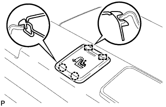
Engage the 2 guides and 2 claws to install the child restraint seat tether anchor cover.
Tech Tips
Use the same procedure for the other 2 child restraint seat tether anchor covers.
-
-
INSTALL CENTER STOP LIGHT SET
-
Connect the connector.
-
Temporarily install the center stop light set.
-
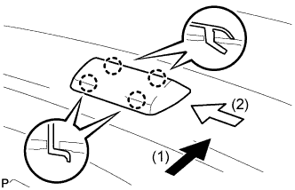
Slide the center stop light set in the order and directions shown by the arrows in the illustration while pushing it towards the rear of the vehicle to engage the 4 claws.
-
-
CONNECT REAR SEAT INNER WITH CENTER BELT ASSEMBLY LH
-
for Type A:
-
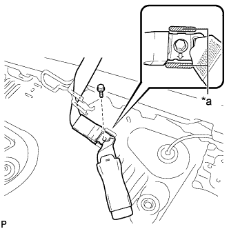
Text in Illustration *a Protruding Part Connect the floor anchor of the rear seat inner with center belt assembly LH with the bolt.
- Torque:
- 42 N*m { 428 kgf*cm, 31 ft.*lbf }
Note
-
Install the rear seat inner with center belt assembly LH with the arrow on the anchor part facing the front of the vehicle.
-
Do not allow the anchor part of the rear seat inner with center belt assembly LH to overlap the protruding parts of the floor panel.
-
-
for Type B:
-
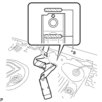
Text in Illustration *a Protruding Part Connect the floor anchor of the rear seat inner with center belt assembly LH with the bolt.
- Torque:
- 42 N*m { 428 kgf*cm, 31 ft.*lbf }
Note
-
Install the rear seat inner with center belt assembly LH with the arrow on the anchor part facing the front of the vehicle.
-
Do not allow the anchor part of the rear seat inner with center belt assembly LH to overlap the protruding parts of the floor panel.
-
-
-
INSTALL CHILD RESTRAINT SEAT ANCHOR BRACKET SUB-ASSEMBLY LH
-
Install the child restraint seat anchor bracket sub-assembly LH with the 2 nuts.
- Torque:
- 18 N*m { 184 kgf*cm, 13 ft.*lbf }
-
-
CONNECT REAR SEAT OUTER BELT ASSEMBLY (for LH Side)
-
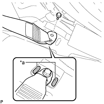
Text in Illustration *a Protruding Part Connect the floor anchor of the rear seat outer belt assembly with the bolt.
- Torque:
- 42 N*m { 428 kgf*cm, 31 ft.*lbf }
Note
Do not allow the anchor part of the rear seat outer belt assembly to overlap the protruding parts of the floor panel.
-
-
CONNECT REAR SEAT OUTER BELT ASSEMBLY (for RH Side)
-
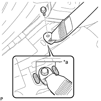
Text in Illustration *a Protruding Part Connect the floor anchor of the rear seat outer belt assembly with the bolt.
- Torque:
- 42 N*m { 428 kgf*cm, 31 ft.*lbf }
Note
Do not allow the anchor part of the rear seat outer belt assembly to overlap the protruding parts of the floor panel.
-
-
INSTALL ROOF HEADLINING ASSEMBLY