HEATED WINDSHIELD DEFROSTER SYSTEM Heated Windshield Defroster System does not operate
DESCRIPTION
-
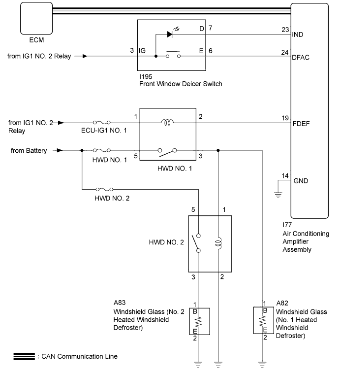
When the front window deicer switch is operated, the operation signal is transmitted to the the air conditioning amplifier assembly directly. When the air conditioning amplifier assembly receives the signal, it turns on the HWD1 relay and HWD2 relay to operate the heated windshield defroster system.
WIRING DIAGRAM
INSPECTION PROCEDURE
Note
-
Inspect the fuses for circuits related to this system before performing the following inspection procedure.
-
If the battery voltage becomes low, heated windshield defroster system operation is canceled to prioritize supplying power to the power steering system. Click here
-
The heated windshield defroster system uses the CAN communication system. First, confirm that there are no malfunctions in the communication system by checking the communication function of the CAN communication system. Refer to the How to Proceed with Troubleshooting procedure Click here.
-
If the ambient temperature is 5°C (41°F) or higher, or if a malfunction of the ambient temperature sensor (thermistor assembly) is detected, the HWD1 relay will be deactivated and the front window deicer switch indicator light will blink.
PROCEDURE
-
CHECK AIR CONDITIONING SYSTEM
-
(a) Check that the air conditioning system can be operated using the remote touch.
Tech Tips
HINT: Both the heated windshield defroster system operation signal and air conditioning system operation signal are transmitted to the air conditioning amplifier assembly through same communication line.
NG 
GO TO AIR CONDITIONING SYSTEM Click here
OK 
-
-
CHECK HEATED WINDSHIELD DEFROSTER SYSTEM
-
Activate the heated windshield defroster system and check the symptoms.
Result Result Proceed to Both heated windshield defrosters do not warm up. A Only No. 1 heated windshield defroster does not warm up. B Only No. 2 heated windshield defroster does not warm up. C
B 
CHECK HARNESS AND CONNECTOR (WINDSHIELD GLASS (NO. 1 HEATED WINDSHIELD DEFROSTER) - HWD NO. 1 RELAY AND BODY GROUND) Click here
C
INSPECT HWD2 RELAY Click here
A
-
-
PERFORM ACTIVE TEST USING GTS
-
Connect the GTS to the DLC3.
-
Turn the engine switch on (IG).
-
Turn the GTS on.
-
Enter the following menus: Body Electrical / Air Conditioner / Active Test.
-
Perform the Active Test according to the display on the GTS.
Air Conditioner Tester Display Test Part Control Range Diagnostic Note HWD Relay HWD relay OFF or ON - OK The heated windshield defroster system operates normally.
NG
INSPECT HWD1 RELAY Click here
OK
-
-
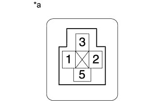
INSPECT FRONT WINDOW DEICER SWITCH
-
Remove the front window deicer switch Click here.
-
Inspect the front window deicer switch Click here.
NG
REPLACE FRONT WINDOW DEICER SWITCH Click here
OK
-
-
CHECK HARNESS AND CONNECTOR (FRONT WINDOW DEICER SWITCH - POWER SUPPLY)
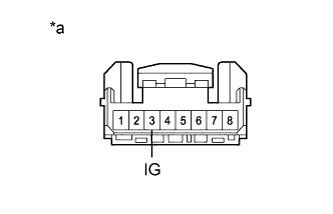
Text in Illustration *a Front view of wire harness connector
(to Front Window Deicer Switch)
-
Measure the voltage according to the value(s) in the table below.
Standard Voltage Tester Connection Condition Specified Condition I195-3 (IG) - Body ground Engine switch off Below 1 V I195-3 (IG) - Body ground Engine switch on (IG) 11 to 14 V
NG
REPAIR OR REPLACE HARNESS OR CONNECTOR
OK
-
-
CHECK HARNESS AND CONNECTOR (FRONT WINDOW DEICER SWITCH - AIR CONDITIONING AMPLIFIER ASSEMBLY)
-
Disconnect the I77 air conditioning amplifier assembly connector.
-
Measure the resistance according to the value(s) in the table below.
Standard Resistance Tester Connection Condition Specified Condition I195-7 (D) - I77-23 (IND) Always Below 1 Ω I195-7 (D) or I77-23 (IND) - Body ground Always 10 kΩ or higher I195-6 (E) - I77-24 (DFAC) Always Below 1 Ω I195-6 (E) or I77-24 (DFAC) - Body ground Always 10 kΩ or higher
NG
REPAIR OR REPLACE HARNESS OR CONNECTOR
OK 
REPLACE AIR CONDITIONING AMPLIFIER ASSEMBLY Click here
-
-
INSPECT HWD1 RELAY
-
Inspect the HWD1 relay Click here.
NG
REPLACE HWD1 RELAY
OK
-
-
CHECK HARNESS AND CONNECTOR (HWD NO. 1 RELAY - POWER SUPPLY)
-
Text in Illustration *a HWD No. 1 Relay Holder Measure the voltage according to the value(s) in the table below.
Standard Voltage Tester Connection Condition Specified Condition HWD1 relay holder terminal-2 - Body ground Engine switch off Below 1 V HWD1 relay holder terminal-2 - Body ground Engine switch on (IG) 11 to 14 V HWD1 relay holder terminal-5 - Body ground Always 11 to 14 V
NG
REPAIR OR REPLACE HARNESS OR CONNECTOR
OK
-
-
CHECK HARNESS AND CONNECTOR (HWD NO. 1 RELAY - AIR CONDITIONING AMPLIFIER ASSEMBLY)
-
Text in Illustration *a HWD No. 1 Relay Holder Disconnect the I77 air conditioning amplifier assembly connector.
-
Measure the resistance according to the value(s) in the table below.
Standard Resistance Tester Connection Condition Specified Condition HWD1 relay holder terminal-1 - I77-19 (FDEF) Always Below 1 Ω HWD1 relay holder terminal-1 or I77-19 (FDEF) - Body ground Always 10 kΩ or higher
NG
REPAIR OR REPLACE HARNESS OR CONNECTOR
OK
-
-
CHECK HARNESS AND CONNECTOR (HWD NO. 1 RELAY - HWD NO. 2 RELAY)
-
Disconnect the A82 windshield glass (No. 1 heated windshield defroster) connector.
-
Remove the HWD No. 2 relay from the No. 2 engine room relay block and junction block assembly.
-
Text in Illustration *a HWD No. 1 Relay and HWD No. 2 Relay Holder Measure the resistance according to the value(s) in the table below.
Standard Resistance Tester Connection Condition Specified Condition HWD1 relay holder terminal-3 - HWD2 relay holder terminal-2 Always Below 1 Ω HWD1 relay holder terminal-3 or HWD2 relay holder terminal-2 - Body ground Always 10 kΩ or higher
NG
REPAIR OR REPLACE HARNESS OR CONNECTOR
OK
REPLACE AIR CONDITIONING AMPLIFIER ASSEMBLY Click here
-
-
CHECK HARNESS AND CONNECTOR (WINDSHIELD GLASS (NO. 1 HEATED WINDSHIELD DEFROSTER) - HWD NO. 1 RELAY AND BODY GROUND)
-
Remove the HWD No. 1 relay and HWD No. 2 relay from the No. 2 engine room relay block and junction block assembly.
-
Disconnect the A82 windshield glass (No. 1 heated windshield defroster) connector.
-
Text in Illustration *a HWD No. 1 Relay and HWD No. 2 Relay Holder Measure the resistance according to the value(s) in the table below.
Standard Resistance Tester Connection Condition Specified Condition HWD1 relay holder terminal-3 - A82-1 (B) Always Below 1 Ω HWD1 relay holder terminal-3 or A82-1 (B) - Body ground Always 10 kΩ or higher A82-2 (E) - Body ground Always Below 1 Ω
NG
REPAIR OR REPLACE HARNESS OR CONNECTOR
OK
REPLACE WINDSHIELD GLASS (HEATED WINDSHIELD DEFROSTER) Click here
-
-
INSPECT HWD2 RELAY
-
Inspect the HWD2 relay Click here.
NG
REPLACE HWD2 RELAY Click here
OK
-
-
CHECK HARNESS AND CONNECTOR (HWD NO. 2 RELAY - POWER SUPPLY)
-
Text in Illustration *a HWD No. 2 Relay Holder Measure the voltage according to the value(s) in the table below.
Standard Voltage Tester Connection Condition Specified Condition HWD2 relay holder terminal-5 - Body ground Always 11 to 14 V
NG
REPAIR OR REPLACE HARNESS OR CONNECTOR
OK
-
-
CHECK HARNESS AND CONNECTOR (HWD NO. 2 RELAY - HWD NO. 1 RELAY AND BODY GROUND)
-
Remove the HWD1 relay from the No. 2 engine room relay block and junction block assembly.
-
Text in Illustration *a HWD No. 1 Relay and HWD No. 2 Relay Holder Measure the resistance according to the value(s) in the table below.
Standard Resistance Tester Connection Condition Specified Condition HWD1 relay holder terminal-3 - HWD2 relay holder terminal-2 Always Below 1 Ω HWD2 relay holder terminal-1 - Body ground Always Below 1 Ω
NG
REPAIR OR REPLACE HARNESS OR CONNECTOR
OK
-
-
CHECK HARNESS AND CONNECTOR (WINDSHIELD GLASS (NO. 2 HEATED WINDSHIELD DEFROSTER) - HWD NO. 2 RELAY AND BODY GROUND
Text in Illustration *a HWD No. 2 Relay Holder
-
Disconnect the A83 windshield glass (heated windshield defroster No. 2) connector.
-
Measure the resistance according to the value(s) in the table below.
Standard Resistance Tester Connection Condition Specified Condition HWD2 relay holder terminal-3 - A83-1 (B) Always Below 1 Ω HWD2 relay holder terminal-3 or A83-1 (B) - Body ground Always 10 kΩ or higher A83-2 (E) - Body ground Always Below 1 Ω
NG
REPAIR OR REPLACE HARNESS OR CONNECTOR
OK
REPLACE WINDSHIELD GLASS (HEATED WINDSHIELD DEFROSTER) Click here
-