INSTRUMENT PANEL SAFETY PAD (for TMC, TMMR Made) DISASSEMBLY
-
REMOVE NO. 1 INSTRUMENT PANEL PIN
-
Remove the 4 screws <D> and 4 No. 1 instrument panel pins.
-
-
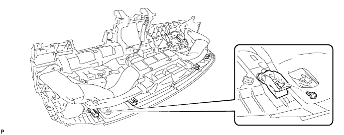
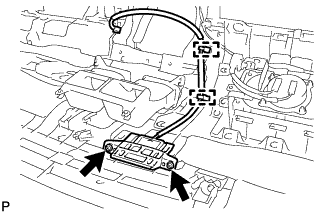
REMOVE INSTRUMENT PANEL PASSENGER AIRBAG ASSEMBLY
CAUTION:
When storing the instrument panel passenger airbag assembly, keep the airbag deployment side facing upward.
-
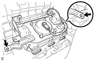
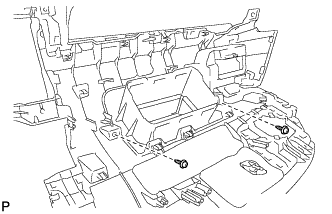
Remove the 2 screws.
-
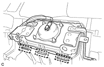
Lean the instrument panel safety pad assembly and disengage the 3 hooks.
-
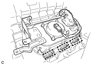
Disengage the 3 hooks to remove the instrument panel passenger airbag assembly from the instrument panel safety pad assembly.
-
-
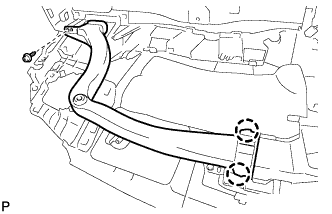
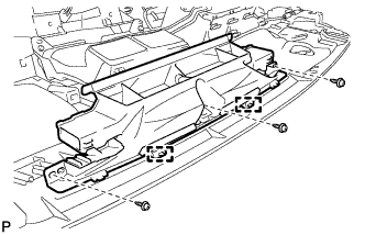
REMOVE NO. 1 HEATER TO REGISTER DUCT (except LHD with Ion Generator)
-
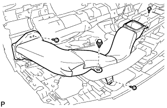
Remove the clip.
-
Remove the 3 screws <D> and No. 1 heater to register duct.
-
-
REMOVE HEATER TO REGISTER DUCT ASSEMBLY (for LHD with Ion Generator)
-
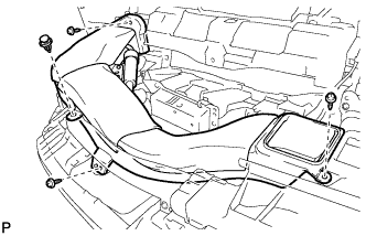
Remove the clip.
-
Remove the 3 screws <D>.
-
Disengage the heater to register duct assembly from the ion generator assembly, to remove the heater to register duct.
-
-
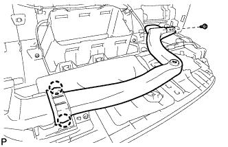
REMOVE NO. 3 HEATER TO REGISTER DUCT (for LHD)
-
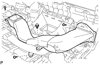
Remove the clip.
-
Remove the 3 screws <D> and No. 3 heater to register duct.
-
-
REMOVE HEATER TO REGISTER DUCT ASSEMBLY (for RHD)
-
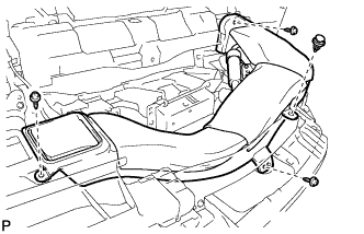
Remove the clip.
-
Remove the 3 screws <D>.
-
Disengage the heater to register duct assembly from the ion generator assembly, to remove the heater to register duct.
-
-
REMOVE ION GENERATOR SUB-ASSEMBLY WITH BRACKET (w/ Ion Generator)
-
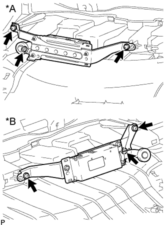
Text in Illustration *A for LHD *B for RHD Remove the 3 screws and ion generator sub-assembly with bracket.
-
-
REMOVE NO. 1 SIDE DEFROSTER NOZZLE DUCT
-
Remove the screw <D>.
-
Disengage the 2 claws to remove the No. 1 side defroster nozzle duct.
-
-
REMOVE NO. 2 SIDE DEFROSTER NOZZLE DUCT
-
Remove the screw <D>.
-
Disengage the 2 claws to remove the No. 2 side defroster nozzle duct.
-
-
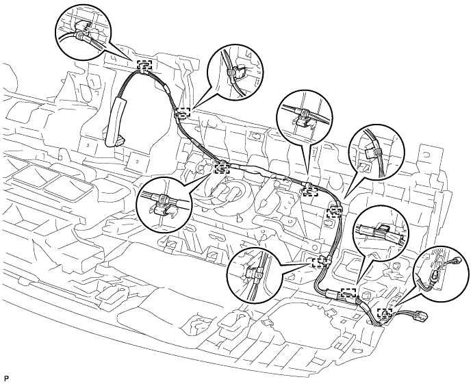
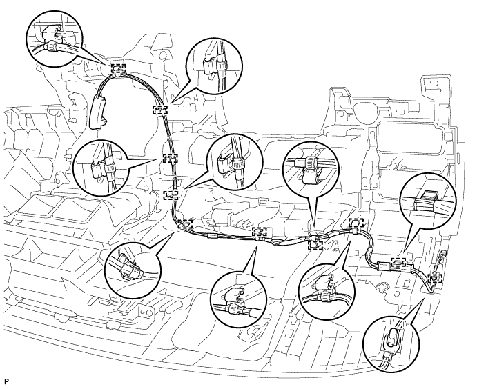
REMOVE ANTENNA CORD SUB-ASSEMBLY
-
for LHD:
-
Disengage the 8 clamps and remove the antenna cord sub-assembly.
-
-
for RHD:
-
Disengage the 10 clamps and remove the antenna cord sub-assembly.
-
-
-
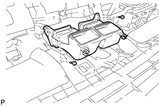
REMOVE DEFROSTER NOZZLE ASSEMBLY
-
Remove the 3 screws <D>.
-
Disengage the 2 guides to remove the defroster nozzle assembly.
-
-
REMOVE NAVIGATION ANTENNA ASSEMBLY (w/ Navigation Antenna)
-
Remove the 2 screws.
-
Disengage the 2 clamps and remove the navigation antenna assembly.
-
-
REMOVE NO. 2 HEATER TO REGISTER DUCT
-
Remove the 2 screws <D> and No. 2 heater to register duct.
-
-
REMOVE NO. 2 INSTRUMENT PANEL GARNISH SUB-ASSEMBLY
-
Remove the 2 screws <D>.
-
Apply protective tape to the areas shown in the illustration.
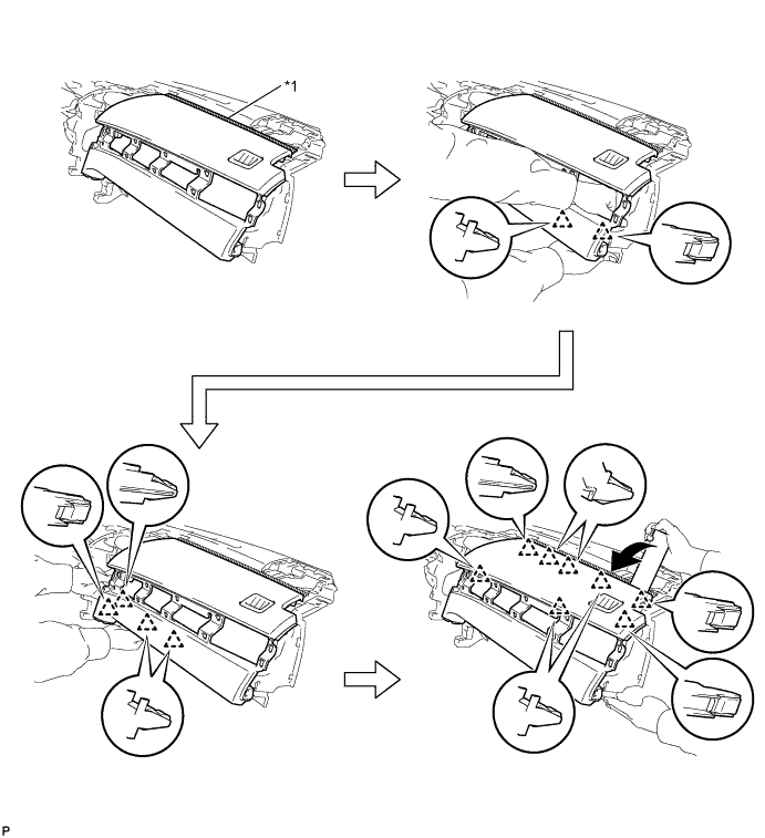
Text in Illustration *1 Protective Tape - - -
Disengage the 6 clips for No. 2 instrument panel garnish sub-assembly lower part as shown in the illustration.
-
Using a moulding remover, disengage the 8 clips to remove the No. 2 instrument panel garnish sub-assembly as shown in the illustration.
-