REAR SUNSHADE SYSTEM Rear Sunshade Shift-linked Function does not Operate when Shift Lever is Moved to R Position
DESCRIPTION
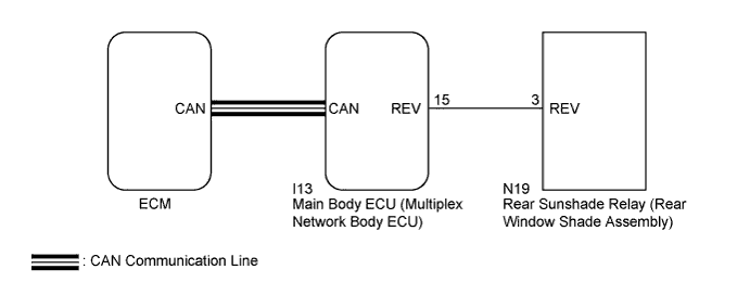
When the engine switch is on (IG) and the shift lever is moved to R, the shift position sensors send a reverse (R) signal to the ECM. Then, the ECM sends this signal to the main body ECU (multiplex network body ECU) via CAN. When the rear sunshade relay (rear window shade assembly) receives this signal with the rear sunshade raised, the rear sunshade is lowered.
WIRING DIAGRAM
INSPECTION PROCEDURE
Note
Since the rear sunshade system has functions that use CAN communication, first confirm that there is no malfunction in the CAN communication system using the How to Proceed with Troubleshooting procedure Click here.
PROCEDURE
-
READ VALUE USING INTELLIGENT TESTER
-
Connect the intelligent tester to the DLC3.
-
Turn the engine switch on (IG).
-
Turn the intelligent tester on.
-
Enter the following menus: Powertrain / Engine / Data List.
-
Read the Data List according to the display on the intelligent tester.
Engine (ECM) Tester Display Measurement Item/Range Normal Condition Diagnostic Note Shift SW Status (R Range) PNP switch status / ON or OFF ON: Shift lever in R
OFF: Shift lever not in R
When the shift lever position displayed on the intelligent tester differs from the actual position, adjustment of the PNP switch or the shift cable may be incorrect. OK The intelligent tester display changes according to the shift state selected using the shift lever.
NG 
GO TO SFI SYSTEM Click here
OK 
-
-
CHECK ECM (REVERSE SIGNAL)
-
Check if the shift position indicator in the combination meter assembly operates normally.
OK The shift position indicator indicates the actual shift position correctly.
NG
REPLACE ECM Click here
OK
-
-
PERFORM ACTIVE TEST USING INTELLIGENT TESTER
-
Connect the intelligent tester to the DLC3.
-
Turn the engine switch on (IG).
-
Turn the intelligent tester on.
-
Enter the following menus: Body / Main Body / Active Test.
-
Perform the Active Test according to the display on the intelligent tester.
Tech Tips
Make sure the rear window shade assembly is raised before performing Active Test.
Main Body (Main Body ECU (Multiplex Network Body ECU)) Tester Display Test Part Control Range Diagnostic Note Reverse Gear Signal Reverse signal OFF/ON - OK The rear window shade assembly is lowered.
NG 
CHECK HARNESS AND CONNECTOR (REVERSE SIGNAL) Click here
OK 
REPLACE MAIN BODY ECU (MULTIPLEX NETWORK BODY ECU) Click here
-
-
CHECK HARNESS AND CONNECTOR (REVERSE SIGNAL)
-
Disconnect the N19 rear sunshade relay (rear window shade assembly) connector.
-
Measure the voltage according to the value(s) in the table below.
Standard Voltage Tester Connection Condition Specified Condition N19-3 (REV) - Body ground Always 11 to 14 V
NG
CHECK HARNESS AND CONNECTOR (REAR SUNSHADE RELAY (REAR WINDOW SHADE ASSEMBLY) - MAIN BODY ECU (MULTIPLEX NETWORK BODY ECU)) Click here
OK
REPLACE REAR SUNSHADE RELAY (REAR WINDOW SHADE ASSEMBLY) Click here
-
-
CHECK HARNESS AND CONNECTOR (REAR SUNSHADE RELAY (REAR WINDOW SHADE ASSEMBLY) - MAIN BODY ECU (MULTIPLEX NETWORK BODY ECU))
-
Disconnect the I13 main body ECU (multiplex network body ECU) connectors.
-
Measure the resistance according to the value(s) in the table below.
Standard Resistance Tester Connection Condition Specified Condition N19-3 (REV) - I13-15 (REV) Always Below 1 Ω I13-15 (REV) - Body ground Always 10 kΩ or higher
NG
REPAIR OR REPLACE HARNESS OR CONNECTOR
OK
REPLACE MAIN BODY ECU (MULTIPLEX NETWORK BODY ECU) Click here
-