POWER OUTLET SOCKET (for TMC, TMMR Made) REMOVAL
-
REMOVE FRONT PANEL GARNISH LH
-
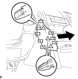
Disengage the 3 clips and 8 guides to remove the front panel garnish LH as shown in the illustration.
-
-
REMOVE FRONT PANEL GARNISH RH
-
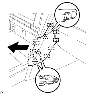
Disengage the 3 clips and 8 guides to remove the front panel garnish RH.
-
-
REMOVE SHIFT LEVER KNOB SUB-ASSEMBLY
-
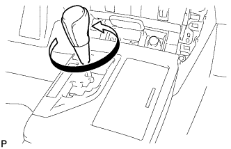
Turn the shift lever knob sub-assembly counterclockwise and remove the shift lever knob sub-assembly.
-
-
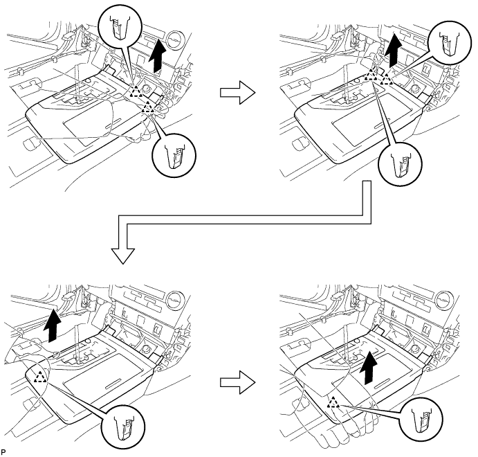
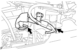
REMOVE REAR CONSOLE UPPER PANEL SUB-ASSEMBLY
-
Move the shift lever to N.
-
Disengage the 6 clips as shown in the illustration.
-
Disconnect each connector to remove the rear console upper panel sub-assembly.
-
-
REMOVE UPPER CONSOLE BOX SUB-ASSEMBLY (w/o Wireless Charger)
-
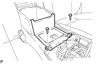
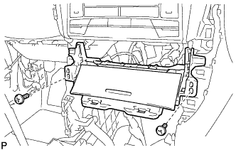
Remove the 2 screws.
-
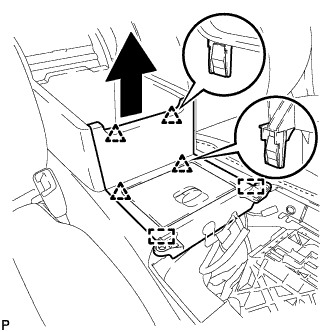
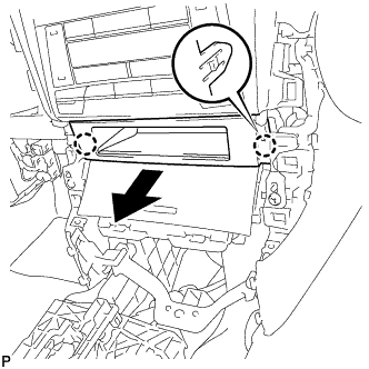
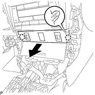
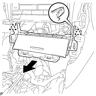
Disengage the 4 clips and 2 guides as shown in the illustration.
-
Disengage the clamp.
-
Disconnect the 2 connectors to remove the upper console box sub-assembly.
-
-
REMOVE NO. 2 POWER OUTLET SOCKET ASSEMBLY (w/o Wireless Charger)
-
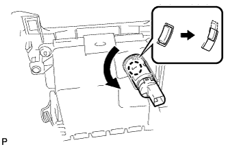
Turn the No. 2 power outlet socket assembly as shown in the illustration to disengage the claw.
-
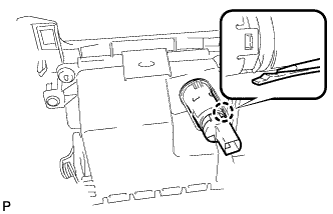
Using a screwdriver, disengage the claw, and then push in the No. 2 power outlet socket assembly until the protrusion of the No. 2 power outlet socket assembly comes into contact with the No. 2 power outlet socket cover.
-
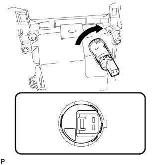
As shown in the illustration, align the protrusion of the No. 2 power outlet socket assembly and the notch of the No. 2 power outlet socket cover.
-
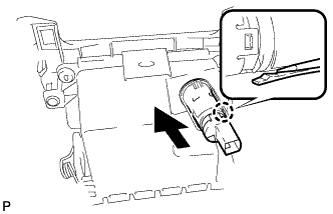
Using a screwdriver, disengage the claw and remove the No. 2 power outlet socket assembly from the No. 2 power outlet socket cover as shown in the illustration.
-
-
REMOVE NO. 2 POWER OUTLET SOCKET COVER (w/o Wireless Charger)
-
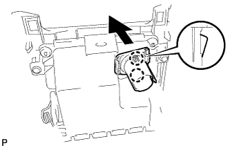
Disengage the 2 claws and remove the No. 2 power outlet socket cover as shown in the illustration.
-
-
REMOVE FRONT CONSOLE UPPER PANEL GARNISH (w/ Wireless Charger)
-
for Blank Type:
-
Disengage the 2 claws and remove the front console upper panel garnish as shown in the illustration.
-
-
for 3 Switch Hole Type:
-
Disengage the 2 claws as shown in the illustration.
-
Disconnect the each connector to remove the front console upper panel garnish.
-
-
-
REMOVE FRONT ASH RECEPTACLE ASSEMBLY (w/ Wireless Charger)
-
Remove the 2 screws <C>.
-
Disengage the 2 clips as shown in the illustration.
-
Disconnect each connector to remove the front ash receptacle assembly.
-
-
REMOVE NO. 1 POWER OUTLET SOCKET ASSEMBLY (w/ Wireless Charger)
-
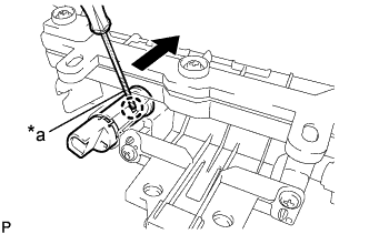
Text in Illustration *a Protective Tape Using a screwdriver, disengage the claw and remove the No. 1 power outlet socket assembly as shown in the illustration.
-
-
REMOVE NO. 1 POWER OUTLET SOCKET COVER (w/ Wireless Charger)
-
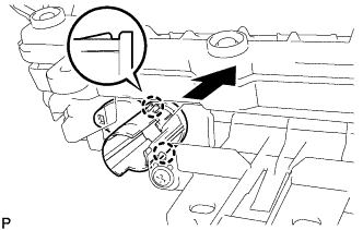
Disengage the 2 claws and remove the No. 1 power outlet socket cover as shown in the illustration.
-