AIR CONDITIONING UNIT (for TMC, TMMR Made) REASSEMBLY
-
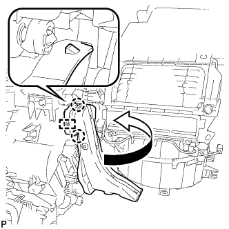
INSTALL NO. 1 COOLER THERMISTOR
-
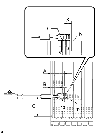
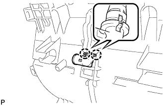
Text in Illustration *a Fixed Part *b Sensor Part Install the No. 1 cooler thermistor as shown in the illustration.
Part Length A 34.3 mm 1.35 in. B 20.9 mm 0.823 in. C 50 mm 1.97 in. Note
-
Be sure to insert the No. 1 cooler thermistor only once because reinserting it into the same position will not allow it to be firmly secured.
-
When reusing the No. 1 cooler evaporator sub-assembly, insert the No. 1 cooler thermistor one row next to the one that has been used previously (X in the illustration).
-
After inserting the No. 1 cooler thermistor, do not apply excessive force to the wire.
-
Directly insert the No. 1 cooler thermistor until the edge of the plastic case "a" comes into contact with the No. 1 cooler evaporator sub-assembly "b".
-
-
-
INSTALL NO. 1 COOLER EVAPORATOR SUB-ASSEMBLY
-
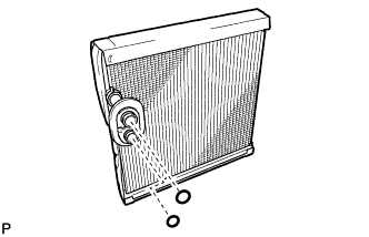
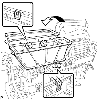
Sufficiently apply compressor oil to 2 new O-rings and the fitting surfaces. Install the 2 O-rings to the No. 1 cooler evaporator sub-assembly.
Compressor Oil ND-OIL 8 or equivalent -
Install the No. 1 cooler evaporator sub-assembly to the blower assembly.
Note
Keep the O-rings and O-ring fitting surfaces free from dirt or any foreign objects.
-
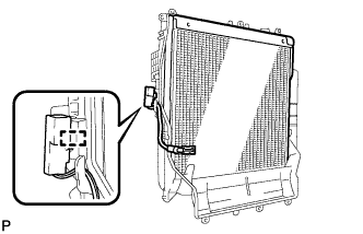
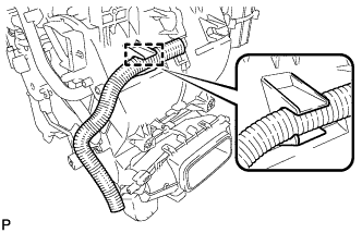
Engage the clamp to install the No. 1 cooler evaporator sub-assembly with the No. 1 cooler thermistor.
Tech Tips
Completely cover the tube with the grommet.
-
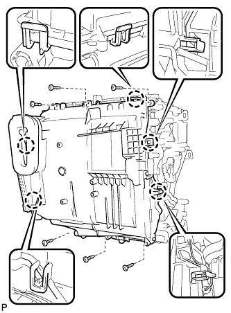
Engage the 5 claws.
-
Install the plate cover with the 6 screws.
-
-
INSTALL HEATER RADIATOR UNIT SUB-ASSEMBLY
-
Install the heater radiator unit sub-assembly to the air conditioner radiator assembly.
-
Install the clamp with the screw.
-
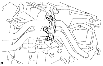
Engage the 3 claws and install the heater clamp.
-
-
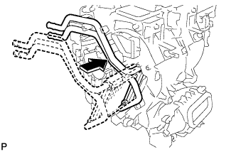
INSTALL QUICK HEATER ASSEMBLY (w/ PTC Heater)
-
Insert the quick heater assembly as shown in the illustration.
-
Install the 2 screws.
-
Engage the 2 clamps.
-
Engage the guide.
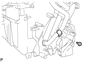
-
Install the quick heater bracket with the screw.
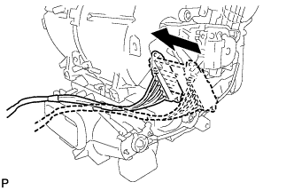
-
Engage the 2 clamps and install the quick heater assembly.
-
-
INSTALL NO. 3 AIR CONDITIONING RADIATOR DAMPER SERVO SUB-ASSEMBLY (for 3 Zone Type)
-
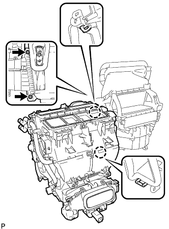
Text in Illustration *a Reference Point Using the reference point, install the No. 3 air conditioning radiator damper servo sub-assembly with the 4 screws.
-
-
INSTALL NO. 2 AIR CONDITIONING RADIATOR DAMPER SERVO SUB-ASSEMBLY
-
Text in Illustration *a Reference Point Using the reference point, install the No. 2 air conditioning radiator damper servo sub-assembly sub-assembly with the 2 screws.
-
-
INSTALL NO. 1 AIR CONDITIONING RADIATOR DAMPER SERVO SUB-ASSEMBLY
-
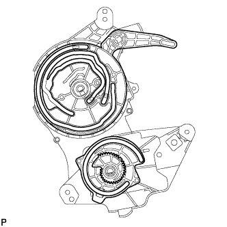
Check that the slots, links and gears of the No. 1 air conditioning radiator damper servo sub-assembly are positioned in the correct orientation as shown in the illustration.
-
Face the contact surfaces of the No. 1 air conditioning radiator damper servo sub-assembly and air conditioning radiator assembly for the No. 1 air conditioning radiator damper servo sub-assembly upward.
-
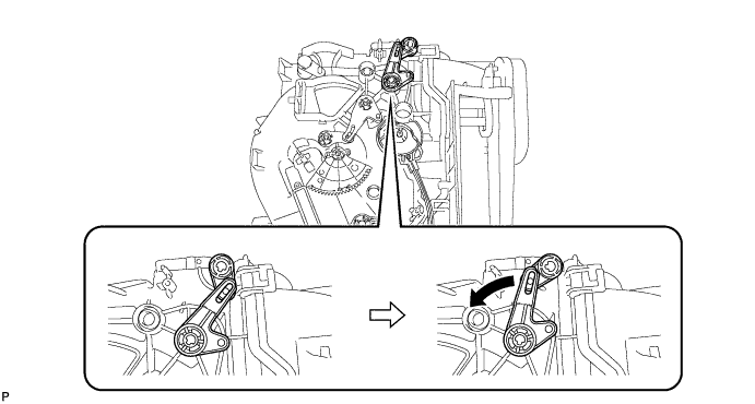
Rotate the link of the air conditioning radiator assembly all the way to the left as shown in the illustration.
-
Rotate the link of the air conditioning radiator assembly to the bottom as shown in the illustration and confirm that the mode switching duct hole is fully closed.
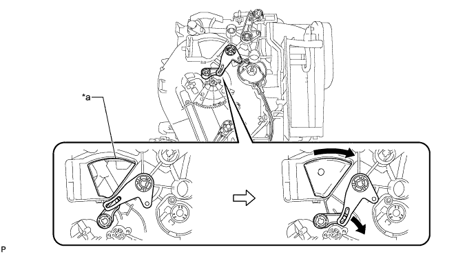
Text in Illustration *a Mode Switching Duct Hole - - -
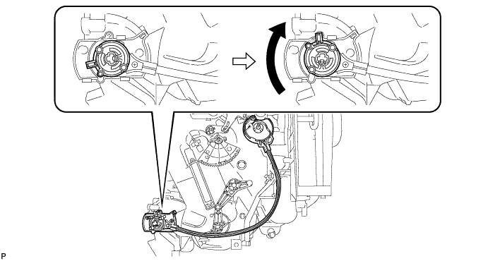
Rotate the lever of the air conditioning radiator assembly to the top as shown in the illustration.
-
Rotate the link of the air conditioning radiator assembly to the in-line position as shown in the illustration.
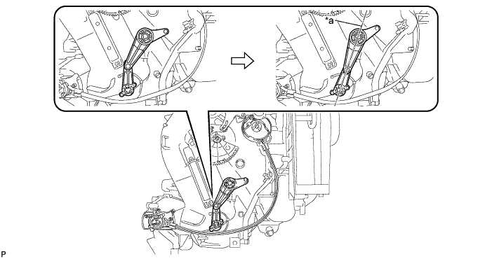
Text in Illustration *a In-line Position - - -
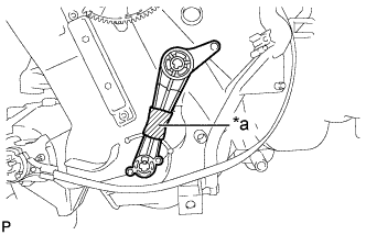
Text in Illustration *a Vinyl Tape Wrap the upper and lower links with vinyl tape to hold them in the in-line position.
-
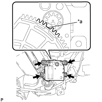
Install the link of the No. 1 air conditioning radiator damper servo sub-assembly to the link guide pin (A) of the air conditioning radiator assembly as shown in the illustration.
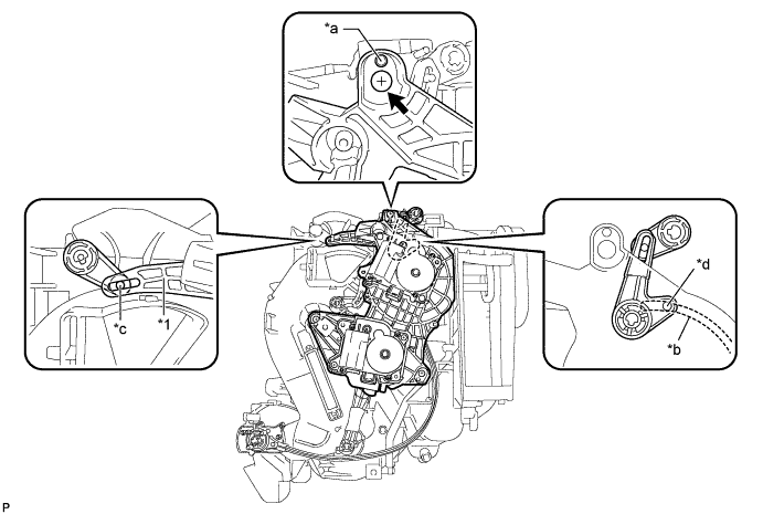
Text in Illustration *1 No. 1 Air Conditioning Radiator Damper Servo Sub-assembly - - *a Guide *b No. 1 Air Conditioning Radiator Damper Servo Sub-assembly Slot *c Link Guide Pin (A) *d Link Guide Pin (B) -
Install the guide hole of the No. 1 air conditioning radiator damper servo sub-assembly to the guide pin of the air conditioning radiator assembly as shown in the illustration.
-
Temporarily install the screw (up to 4 or 5 threads).
Note
-
Make sure that the link guide pin (B) is inserted in the No. 1 air conditioning radiator damper servo sub-assembly slot.
-
Avoid tilting the air conditioning radiator assembly during installation. This helps to prevent the link guide pins from coming out of position.
-
-
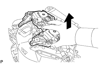
Lift the No. 1 air conditioning radiator damper servo sub-assembly slightly to create clearance.
-
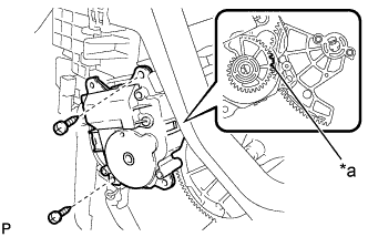
Move the air conditioning radiator assembly gear so that the alignment holes of the No. 1 air conditioning radiator damper servo sub-assembly and air conditioning radiator assembly are aligned.
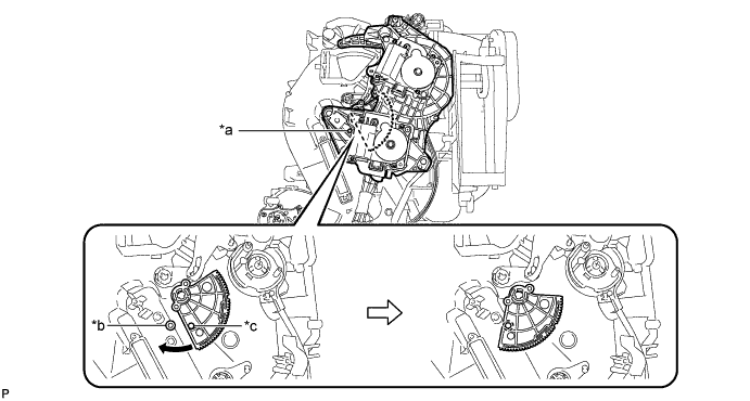
Text in Illustration *a No. 1 Air Conditioning Radiator Damper Servo Sub-assembly Alignment Hole *b Air Conditioning Radiator Assembly Alignment Hole *c Air Conditioning Radiator Assembly Alignment Gear Alignment Hole - - -
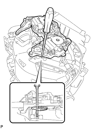
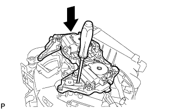
Insert a screwdriver into the alignment holes as shown in the illustration.
-
Make sure that all the links and gears are in the positions shown in the illustration.
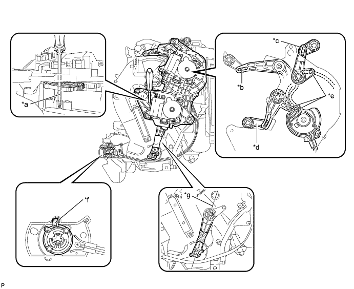
Text in Illustration *a Screwdriver is inserted into alignment holes. *b Link guide pin is inserted. *c Link is positioned to left side. *d Link is positioned at bottom. *e Each link guide pin is inserted in its No. 1 air conditioning radiator damper servo sub-assembly slot. *f Lever is positioned at top. *g Links are in-line. - - -
Push the loose fitting No. 1 air conditioning radiator damper servo sub-assembly into position.
Note
-
Make sure that the No. 1 air conditioning radiator damper servo sub-assembly are fully pushed into position.
-
After pushing the servos into position, keep them in place by holding them until the screws are installed.
Tech Tips
Push the No. 1 air conditioning radiator damper servo sub-assembly until a click sound is heard.
-
-
Remove the screwdriver.
-
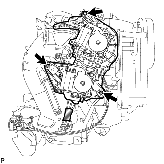
Fully install the top screw, and then install the No. 1 air conditioning radiator damper servo sub-assembly with the 2 screws.
-
Remove the vinyl tape.
-
-
INSTALL DRAIN COOLER HOSE
-
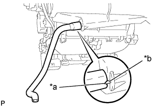
Text in Illustration *a Hose Notch *b Air Conditioning Radiator Assembly Rib Install the drain cooler hose to the air conditioning radiator assembly as shown in the illustration.
-
-
INSTALL AIR CONDITIONING RADIATOR ASSEMBLY
-
Engage the 2 claws.
-
Install the air conditioning radiator assembly with the 2 screws.
-
-
INSTALL COOLER EXPANSION VALVE
-
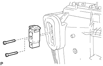
Using a 4 mm hexagon socket wrench, install the cooler expansion valve with the 2 hexagon bolts.
- Torque:
- 3.5 N*m { 36 kgf*cm, 31 in.*lbf }
-
-
INSTALL AIR CONDITIONING HARNESS ASSEMBLY (for Dual Type)
-
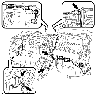
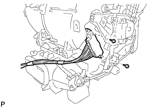
Engage the 7 clamps to install the air conditioning harness assembly.
-
Connect the 5 connectors.
-
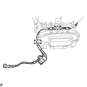
Install the heater packing as shown in the illustration.
-
-
INSTALL AIR CONDITIONING HARNESS ASSEMBLY (for 3 Zone Type)
-
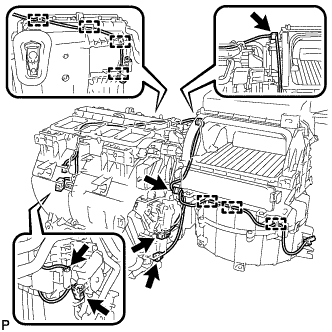
Engage the 7 clamps to install the air conditioning harness assembly.
-
Connect the 6 connectors.
-
Install the heater packing as shown in the illustration.
-
-
INSTALL ASPIRATOR
-
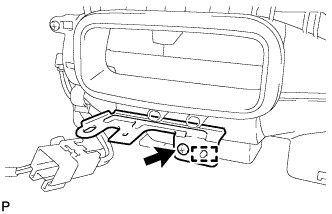
Engage the 2 claws to install the aspirator.
-
-
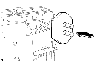
INSTALL COOLER THERMISTOR HOSE
-
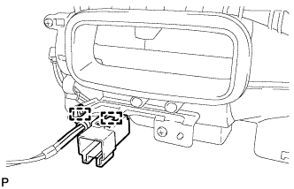
Engage the clamp to install the cooler thermistor hose.
-
-
INSTALL NO. 6 HEATER TO REGISTER DUCT ASSEMBLY
-
Engage the 2 claws and 2 guides to install the No. 6 heater to register duct assembly as shown in the illustration.
-
-
INSTALL NO. 1 AIR DUCT SUB-ASSEMBLY
-
Engage the guide and 2 claws to install the No. 1 air duct sub-assembly as shown in the illustration.
-