CENTER AIRBAG SENSOR ASSEMBLY (for TMMK Made) REMOVAL
-
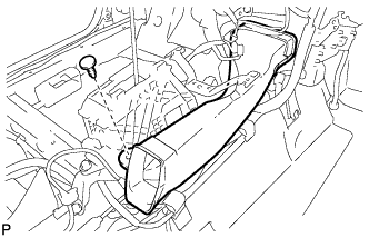
REMOVE LOWER NO. 2 INSTRUMENT PANEL AIRBAG ASSEMBLY
-
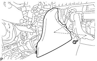
REMOVE REAR CONSOLE BOX ASSEMBLY
-
REMOVE FRONT DOOR SCUFF PLATE LH
-
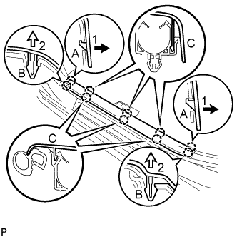
Disengage the 2 claws (A) in the direction indicated by the arrows (1) shown in the illustration.
-
Disengage the 2 claws (B) in the direction indicated by the arrows (2) shown in the illustration.
-
Disengage the 6 claws (C) to remove the front door scuff plate LH.
-
-
REMOVE COWL SIDE TRIM SUB-ASSEMBLY LH
-
Remove the clip.
-
Pull the cowl side trim sub-assembly LH as shown in the illustration to disengage the 2 clips and remove the cowl side trim sub-assembly LH.
-
-
DISCONNECT FRONT DOOR OPENING TRIM WEATHERSTRIP LH
Tech Tips
Disconnect the front door opening trim weatherstrip LH to the extent that allows the removal of the instrument side panel LH.
-
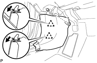
REMOVE INSTRUMENT SIDE PANEL LH
-
Using a moulding remover, disengage the 4 claws as shown in the illustration.
-
Disengage the 3 guides and remove the instrument side panel LH as shown in the illustration.
-
-
DISCONNECT HOOD LOCK CONTROL LEVER SUB-ASSEMBLY
-
Disengage the claw and 2 guides to disconnect the hood lock control lever sub-assembly.
-
-
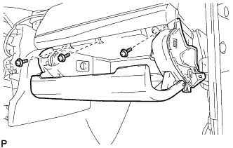
REMOVE LOWER NO. 1 INSTRUMENT PANEL FINISH PANEL ASSEMBLY
-
Remove the bolt <B> and screw <C> or <D>.
-
Disengage the 4 claws, 9 clips and 3 guides to remove the lower No. 1 instrument panel finish panel assembly.
-
-
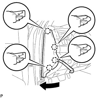
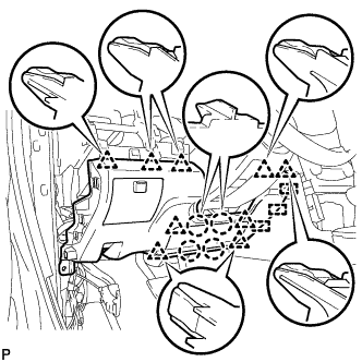
REMOVE LOWER INSTRUMENT PANEL SUB-ASSEMBLY
-
Remove the 2 screws <C> or <D>.
-
Open the lower instrument panel door.
-
Remove the 3 screws <C> or <D>.
-
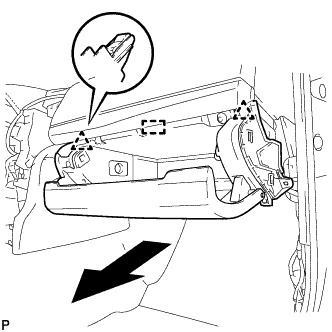
Disengage the 2 clips and guide as shown in the illustration.
-
Disengage the clamp.
-
Disengage the glove compartment light as shown in the illustration.
-
Disconnect the connector and remove the lower instrument panel sub-assembly.
-
-
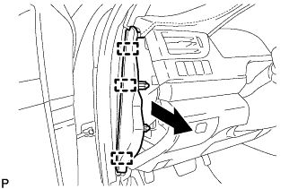
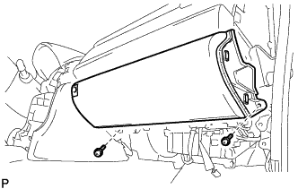
REMOVE UPPER CONSOLE PANEL SUB-ASSEMBLY
-
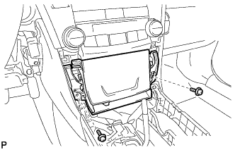
Remove the 2 screws <C> or <D>.
-
Disengage the 2 clips and guide as shown in the illustration.
-
Disconnect each connector to remove the upper console panel sub-assembly.
-
-
REMOVE FRONT NO. 2 CONSOLE BOX INSERT
-
Disengage the 2 claws to disconnect the room temperature sensor from the front No. 2 console box insert.
-
Remove the screw <C> or <D>.
-
Disengage the 2 clips and guide to remove the front No. 2 console box insert as shown in the illustration.
-
-
REMOVE CONSOLE BOX INSERT
-
Remove the screw <C> or <D>.
-
Disengage the 2 clips and guide to remove the console box insert as shown in the illustration.
-
-
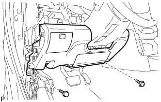
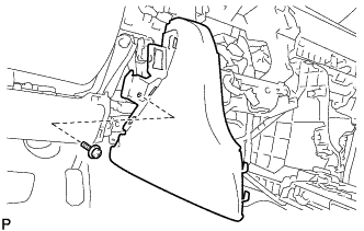
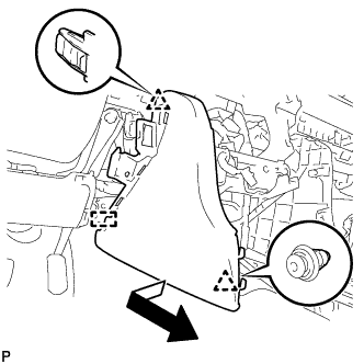
REMOVE FLOOR CARPET BRACKET LH
-
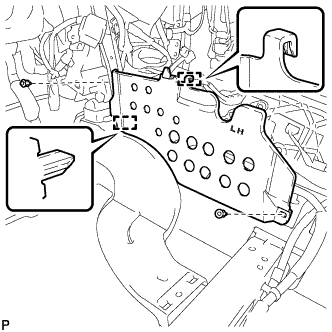
Remove the 2 clips.
-
Disengage the 2 guides to remove the floor carpet bracket LH.
-
-
REMOVE FLOOR CARPET BRACKET RH
-
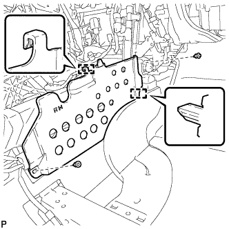
Remove the 2 clips.
-
Disengage the 2 guides to remove the floor carpet bracket RH.
-
-
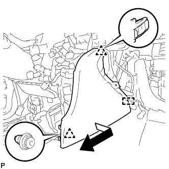
REMOVE NO. 1 CONSOLE BOX DUCT
-
Remove the clip and No. 1 console box duct.
-
-
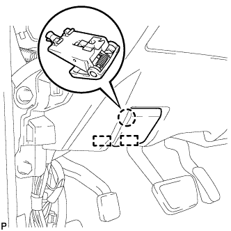
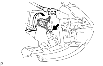
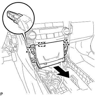
REMOVE AIRBAG SENSOR ASSEMBLY
-
Check that the engine switch is off.
-
Check that the cable is disconnected from the negative (-) battery terminal.
CAUTION:
Wait at least 90 seconds after disconnecting the cable from the negative (-) battery terminal to disable the SRS system.
-
Turn back the carpet.
-
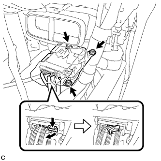
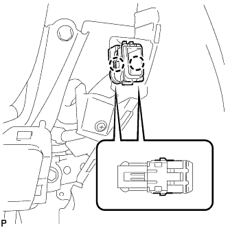
Disconnect the connectors from the airbag sensor assembly as shown in the illustration.
Note
When disconnecting any airbag connector, take care not to damage the airbag wire harness.
-
Remove the 3 bolts and airbag sensor assembly.
-