AIRBAG SYSTEM (for TMMK Made), Diagnostic DTC:B1650/32
| DTC Code | DTC Name |
|---|---|
| B1650/32 | Occupant Classification System Malfunction |
DESCRIPTION
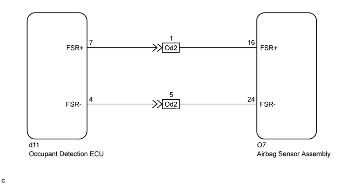
The occupant classification system circuit consists of the airbag sensor assembly and occupant classification system.
If the airbag sensor assembly receives signals from the occupant detection ECU, it determines whether the front passenger airbag and front passenger side knee airbag should be operated.
DTC B1650/32 is stored when a malfunction is detected in the occupant classification system circuit.
| DTC No. | DTC Detection Condition | Trouble Area |
|---|---|---|
| B1650/32 |
|
|
WIRING DIAGRAM
INSPECTION PROCEDURE
Note
After turning the engine switch off, waiting time may be required before disconnecting the cable from the negative (-) battery terminal. Therefore, make sure to read the disconnecting the cable from the negative (-) battery terminal notices before proceeding with work Click here.
PROCEDURE
-
CHECK DTC (OCCUPANT DETECTION ECU)
-
Check for DTCs of the occupant detection ECU Click here.
OK DTC is not output.
NG 
GO TO OCCUPANT CLASSIFICATION SYSTEM Click here
OK 
-
-
CHECK CONNECTORS
-
Turn the engine switch off.
-
Disconnect the cable from the negative (-) battery terminal.
CAUTION:
Wait at least 90 seconds after disconnecting the cable from the negative (-) battery terminal to disable the SRS system.
-
Check that the connectors are properly connected to the airbag sensor assembly and occupant detection ECU. Also check that the connectors that link the No. 2 floor wire and front seat wire RH are properly connected.
OK The connectors are properly connected. Tech Tips
If the connectors are not connected securely, reconnect the connectors and proceed to the next inspection.
-
Disconnect the connectors from the airbag sensor assembly and occupant detection ECU. Also disconnect the connectors that link the No. 2 floor wire and front seat wire RH.
-
Check that the terminals of the connectors are not damaged.
OK The terminals are not deformed or damaged.
NG
REPLACE WIRE HARNESS
OK
-
-
CHECK OCCUPANT CLASSIFICATION SYSTEM CIRCUIT (OPEN)
-
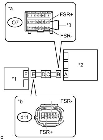
Text in Illustration *1 Occupant Detection ECU *2 Airbag Sensor Assembly *3 Service Wire *a Front view of wire harness connector
(to Airbag Sensor Assembly)
*b Front view of wire harness connector
(to Occupant Detection ECU)
Connect the connectors that link the No. 2 floor wire and front seat wire RH.
-
Using a service wire, connect terminals 16 (FSR+) and 24 (FSR-) of connector B.
Note
Do not forcibly insert the service wire into the terminals of the connector when connecting the wire.
-
Measure the resistance according to the value(s) in the table below.
Standard Resistance Tester Connection Condition Specified Condition d11-7 (FSR+) - d11-4 (FSR-) Always Below 1 Ω
NG 
CHECK NO. 2 FLOOR WIRE (OPEN) Click here
OK
-
-
CHECK OCCUPANT CLASSIFICATION SYSTEM CIRCUIT (SHORT)
-
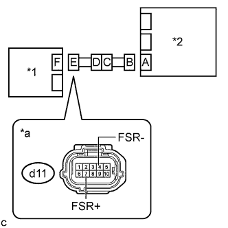
Text in Illustration *1 Occupant Detection ECU *2 Airbag Sensor Assembly *a Front view of wire harness connector
(to Occupant Detection ECU)
Disconnect the service wire from connector B.
-
Measure the resistance according to the value(s) in the table below.
Standard Resistance Tester Connection Condition Specified Condition d11-7 (FSR+) - d11-4 (FSR-) Always 1 MΩ or higher
NG
CHECK NO. 2 FLOOR WIRE (SHORT) Click here
OK
-
-
CHECK OCCUPANT CLASSIFICATION SYSTEM CIRCUIT (SHORT TO B+)
-
Text in Illustration *1 Occupant Detection ECU *2 Airbag Sensor Assembly *a Front view of wire harness connector
(to Occupant Detection ECU)
Connect the cable to the negative (-) battery terminal.
-
Turn the engine switch on (IG).
-
Measure the voltage according to the value(s) in the table below.
Standard Voltage Tester Connection Condition Specified Condition d11-7 (FSR+) - Body ground Engine switch on (IG) Below 1 V d11-4 (FSR-) - Body ground Engine switch on (IG) Below 1 V -
Turn the engine switch off.
-
Disconnect the cable from the negative (-) battery terminal.
CAUTION:
Wait at least 90 seconds after disconnecting the cable from the negative (-) battery terminal to disable the SRS system.
NG
CHECK NO. 2 FLOOR WIRE (SHORT TO B+) Click here
OK
-
-
CHECK OCCUPANT CLASSIFICATION SYSTEM CIRCUIT (SHORT TO GROUND)
-
Text in Illustration *1 Occupant Detection ECU *2 Airbag Sensor Assembly *a Front view of wire harness connector
(to Occupant Detection ECU)
Measure the resistance according to the value(s) in the table below.
Standard Resistance Tester Connection Condition Specified Condition d11-7 (FSR+) - Body ground Always 1 MΩ or higher d11-4 (FSR-) - Body ground Always 1 MΩ or higher
NG
CHECK NO. 2 FLOOR WIRE (SHORT TO GROUND) Click here
OK 
REPLACE AIRBAG SENSOR ASSEMBLY Click here
-
-
CHECK NO. 2 FLOOR WIRE (OPEN)
-
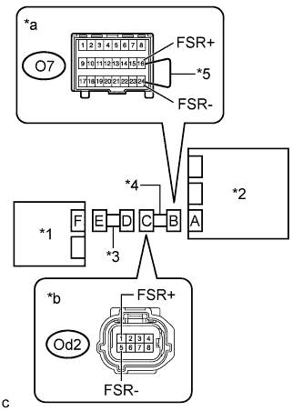
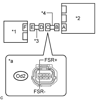
Text in Illustration *1 Occupant Detection ECU *2 Airbag Sensor Assembly *3 Front Seat Wire RH *4 No. 2 Floor Wire *5 Service Wire *a Front view of wire harness connector
(to Airbag Sensor Assembly)
*b Front view of wire harness connector
(to Front Seat Wire RH)
Disconnect the front seat wire RH from the No. 2 floor wire.
Tech Tips
The service wire has already been inserted into connector B.
-
Measure the resistance according to the value(s) in the table below.
Standard Resistance Tester Connection Condition Specified Condition Od2-1 (FSR+) - Od2-5 (FSR-) Always Below 1 Ω -
Disconnect the service wire from connector B.
NG
REPLACE NO. 2 FLOOR WIRE
OK
REPLACE FRONT SEAT WIRE RH
-
-
CHECK NO. 2 FLOOR WIRE (SHORT)
-
Text in Illustration *1 Occupant Detection ECU *2 Airbag Sensor Assembly *3 Front Seat Wire RH *4 No. 2 Floor Wire *a Front view of wire harness connector
(to Front Seat Wire RH)
Disconnect the front seat wire RH from the No. 2 floor wire.
-
Measure the resistance according to the value(s) in the table below.
Standard Resistance Tester Connection Condition Specified Condition Od2-1 (FSR+) - Od2-5 (FSR-) Always 1 MΩ or higher
NG
REPLACE NO. 2 FLOOR WIRE
OK
REPLACE FRONT SEAT WIRE RH
-
-
CHECK NO. 2 FLOOR WIRE (SHORT TO B+)
-
Text in Illustration *1 Occupant Detection ECU *2 Airbag Sensor Assembly *3 Front Seat Wire RH *4 No. 2 Floor Wire *a Front view of wire harness connector
(to Front Seat Wire RH)
Disconnect the front seat wire RH from the No. 2 floor wire.
-
Connect the cable to the negative (-) battery terminal.
-
Turn the engine switch on (IG).
-
Measure the voltage according to the value(s) in the table below.
Standard Voltage Tester Connection Condition Specified Condition Od2-1 (FSR+) - Body ground Engine switch on (IG) Below 1 V Od2-5 (FSR-) - Body ground Engine switch on (IG) Below 1 V
NG
REPLACE NO. 2 FLOOR WIRE
OK
REPLACE FRONT SEAT WIRE RH
-
-
CHECK NO. 2 FLOOR WIRE (SHORT TO GROUND)
-
Text in Illustration *1 Occupant Detection ECU *2 Airbag Sensor Assembly *3 Front Seat Wire RH *4 No. 2 Floor Wire *a Front view of wire harness connector
(to Front Seat Wire RH)
Disconnect the front seat wire RH from the No. 2 floor wire.
-
Measure the resistance according to the value(s) in the table below.
Standard Resistance Tester Connection Condition Specified Condition Od2-1 (FSR+) - Body ground Always 1 MΩ or higher Od2-5 (FSR-) - Body ground Always 1 MΩ or higher
NG
REPLACE NO. 2 FLOOR WIRE
OK
REPLACE FRONT SEAT WIRE RH
-