LIGHTING SYSTEM Interior Light Circuit
DESCRIPTION
The main body ECU (multiplex network body ECU) controls the operation of the following lights:
-
Personal Light*2, *3
-
Rear Interior Light
-
Ignition Key Cylinder Light*1
Tech Tips
The light cut relay supplies power to the lights not controlled by the illuminated entry system. If all the lights that use power from the light cut relay do not turn on, check the light cut relay circuit first Click here.
-
*1: w/o Smart Entry and Start System
-
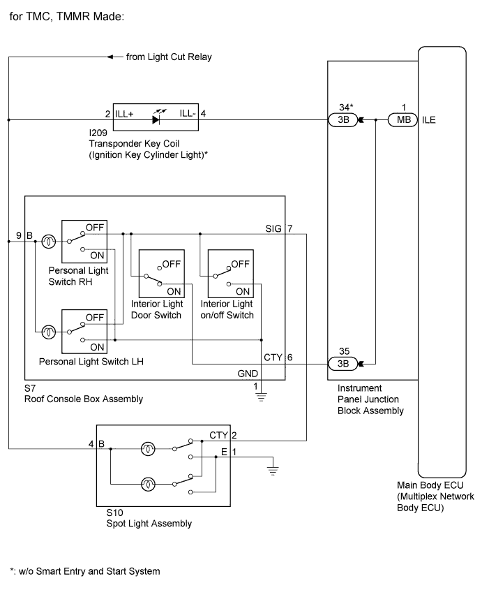
*2: for TMC, TMMR Made
-
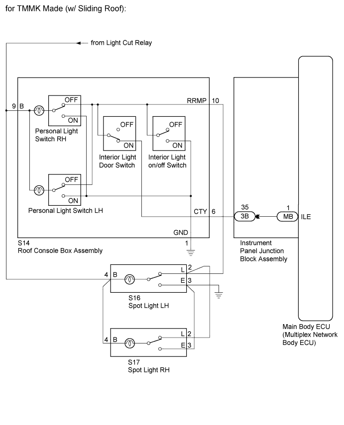
*3: for TMMK Made (w/ Sliding Roof)
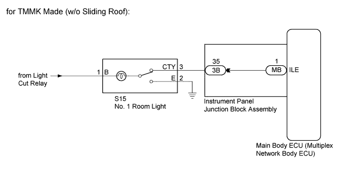
WIRING DIAGRAM
INSPECTION PROCEDURE
Note
Inspect the fuses for circuits related to this system before performing the following inspection procedure.
PROCEDURE
-
PERFORM ACTIVE TEST USING INTELLIGENT TESTER
-
Connect the intelligent tester to the DLC3.
-
Turn the ignition switch to ON.
-
Turn the intelligent tester on.
-
Enter the following menus: Body / Main Body / Active Test.
-
Perform the Active Test according to the display on the intelligent tester.
Main Body Tester Display Test Part Control Range Diagnostic Note Illuminated Entry System Personal light*1, *2 and rear interior light ON/OFF
-
No. 1 room light switch in DOOR position*3
-
Interior light door switch is on*1, *2
-
*1: for TMC, TMMR Made
-
*2: for TMMK Made (w/ Sliding Roof)
-
*3: for TMMK Made (w/o Sliding Roof)
OK Each light fades in. Result Result Proceed to OK A NG (w/o Smart Entry and Start System)*1 B NG (w/ Smart Entry and Start System)*1, *2 C NG (w/ Smart Entry and Start System)*3 D
-
*1: for TMC, TMMR Made
-
*2: for TMMK Made (w/ Sliding Roof)
-
*3: for TMMK Made (w/o Sliding Roof)
-
B 
CHECK HARNESS AND CONNECTOR (LIGHT CUT RELAY - INSTRUMENT PANEL JUNCTION BLOCK ASSEMBLY) Click here
C
CHECK HARNESS AND CONNECTOR (LIGHT CUT RELAY - INSTRUMENT PANEL JUNCTION BLOCK ASSEMBLY) Click here
D
CHECK HARNESS AND CONNECTOR (LIGHT CUT RELAY - INSTRUMENT PANEL JUNCTION BLOCK ASSEMBLY) Click here
A 
PROCEED TO NEXT SUSPECTED AREA SHOWN IN PROBLEM SYMPTOMS TABLE Click here
-
-
CHECK HARNESS AND CONNECTOR (LIGHT CUT RELAY - INSTRUMENT PANEL JUNCTION BLOCK ASSEMBLY)
-
Disconnect the 3B instrument panel junction block assembly connector.
-
Measure the voltage according to the value(s) in the table below.
Tech Tips
Perform the check under the following condition:
-
Interior light door switch on
-
Personal light switch off
Standard Voltage Tester Connection Condition Specified Condition 3B-34 - Body ground Always 11 to 14 V 3B-35 - Body ground Always 11 to 14 V Result Result Proceed to OK A NG (Voltage is not present at terminal 3B-34) B NG (Voltage is not present at terminal 3B-35) C -
B
CHECK HARNESS AND CONNECTOR (LIGHT CUT RELAY - TRANSPONDER KEY COIL) Click here
C
CHECK HARNESS AND CONNECTOR (LIGHT CUT RELAY - ROOF CONSOLE BOX ASSEMBLY) Click here
A 
-
-
INSPECT INSTRUMENT PANEL JUNCTION BLOCK ASSEMBLY
-
Remove the instrument panel junction block assembly Click here.
-
Remove the main body ECU (multiplex network body ECU) from the instrument panel junction block assembly.
-
Measure the resistance according to the value(s) in the table below.
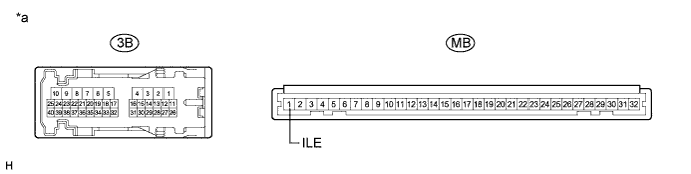
Text in Illustration *a Component without harness connected
(Instrument Panel Junction Block Assembly)
- - Standard Resistance Tester Connection Condition Specified Condition 3B-34 - MB-1 (ILE) Always Below 1 Ω 3B-35 - MB-1 (ILE) Always Below 1 Ω
NG 
REPLACE INSTRUMENT PANEL JUNCTION BLOCK ASSEMBLY Click here
OK
REPLACE MAIN BODY ECU (MULTIPLEX NETWORK BODY ECU) Click here
-
-
CHECK HARNESS AND CONNECTOR (LIGHT CUT RELAY - TRANSPONDER KEY COIL)
-
Disconnect the I191 transponder key coil connector.
-
Measure the voltage according to the value(s) in the table below.
Standard Voltage Tester Connection Condition Specified Condition I191-2 (ILL+) - Body ground Always 11 to 14 V
NG
REPAIR OR REPLACE HARNESS OR CONNECTOR
OK
-
-
INSPECT TRANSPONDER KEY COIL
-
Remove the transponder key coil Click here.
-
Inspect the transponder key coil Click here.
OK Transponder key coil is normal.
NG
REPLACE TRANSPONDER KEY COIL Click here
OK
-
-
CHECK HARNESS AND CONNECTOR (TRANSPONDER KEY COIL - INSTRUMENT PANEL JUNCTION BLOCK ASSEMBLY)
-
Measure the resistance according to the value(s) in the table below.
Standard Resistance Tester Connection Condition Specified Condition I191-4 (ILL-) - 3B-34 Always Below 1 Ω I191-4 (ILL-) - Body ground Always 10 kΩ or higher
NG
REPAIR OR REPLACE HARNESS OR CONNECTOR
OK
USE SIMULATION METHOD TO CHECK Click here
-
-
CHECK HARNESS AND CONNECTOR (LIGHT CUT RELAY - ROOF CONSOLE BOX ASSEMBLY)
-
Disconnect the S7 roof console box assembly connector.
-
Measure the voltage according to the value(s) in the table below.
Standard Voltage Tester Connection Condition Specified Condition S7-9 (B) - Body ground Always 11 to 14 V
NG
REPAIR OR REPLACE HARNESS OR CONNECTOR
OK
-
-
INSPECT ROOF CONSOLE BOX ASSEMBLY
-
Remove the roof console box assembly Click here.
-
Inspect the roof console box assembly Click here.
OK Roof console box assembly is normal.
NG
REPLACE ROOF CONSOLE BOX ASSEMBLY Click here
OK
-
-
CHECK HARNESS AND CONNECTOR (ROOF CONSOLE BOX ASSEMBLY - INSTRUMENT PANEL JUNCTION BLOCK ASSEMBLY)
-
Measure the resistance according to the value(s) in the table below.
Standard Resistance Tester Connection Condition Specified Condition S7-6 (CTY) - 3B-35 Always Below 1 Ω S7-6 (CTY) - Body ground Always 10 kΩ or higher
NG
REPAIR OR REPLACE HARNESS OR CONNECTOR
OK
USE SIMULATION METHOD TO CHECK Click here
-
-
CHECK HARNESS AND CONNECTOR (LIGHT CUT RELAY - INSTRUMENT PANEL JUNCTION BLOCK ASSEMBLY)
-
Disconnect the 3B instrument panel junction block assembly connector.
-
Measure the voltage according to the value(s) in the table below.
Tech Tips
Perform the check under the following conditions:
-
Interior light door switch on
-
Personal light switch off
Standard Voltage Tester Connection Condition Specified Condition 3B-35 - Body ground Always 11 to 14 V -
NG
CHECK HARNESS AND CONNECTOR (LIGHT CUT RELAY - ROOF CONSOLE BOX ASSEMBLY) Click here
OK
-
-
INSPECT INSTRUMENT PANEL JUNCTION BLOCK ASSEMBLY
-
Remove the instrument panel junction block assembly Click here.
-
Remove the main body ECU (multiplex network body ECU) from the instrument panel junction block assembly.
-
Measure the resistance according to the value(s) in the table below.
Text in Illustration *a Component without harness connected
(Instrument Panel Junction Block Assembly)
- - Standard Resistance Tester Connection Condition Specified Condition 3B-35 - MB-1 (ILE) Always Below 1 Ω
NG
REPLACE INSTRUMENT PANEL JUNCTION BLOCK ASSEMBLY Click here
OK
REPLACE MAIN BODY ECU (MULTIPLEX NETWORK BODY ECU) Click here
-
-
CHECK HARNESS AND CONNECTOR (LIGHT CUT RELAY - ROOF CONSOLE BOX ASSEMBLY)
-
Disconnect the S7*1, S14*2 roof console box assembly connector.
-
Measure the voltage according to the value(s) in the table below.
Standard Voltage Tester Connection Condition Specified Condition S7-9 (B) - Body ground*1 Always 11 to 14 V S14-9 (B) - Body ground*2 Always 11 to 14 V
-
*1: for TMC, TMMR Made
-
*2: for TMMK Made
-
NG
REPAIR OR REPLACE HARNESS OR CONNECTOR
OK
-
-
INSPECT ROOF CONSOLE BOX ASSEMBLY
-
Remove the roof console box assembly (for TMC, TMMR Made) Click here.
-
Remove the roof console box assembly (for TMMK Made) Click here.
-
Inspect the roof console box assembly (for TMMK Made) Click here.
-
Inspect the roof console box assembly (for TMC, TMMR Made) Click here.
OK Roof console box assembly is normal. Result Result Proceed to OK A NG (for TMC, TMMR Made) B NG (for TMMK Made) C
B
REPLACE ROOF CONSOLE BOX ASSEMBLY Click here
C
REPLACE ROOF CONSOLE BOX ASSEMBLY Click here
A
-
-
CHECK HARNESS AND CONNECTOR (ROOF CONSOLE BOX ASSEMBLY - INSTRUMENT PANEL JUNCTION BLOCK ASSEMBLY)
-
Measure the resistance according to the value(s) in the table below.
Standard Resistance Tester Connection Condition Specified Condition S7-6 (CTY) - 3B-35*1 Always Below 1 Ω S14-6 (CTY) - 3B-35*2 Always Below 1 Ω S7-6 (CTY) - Body ground*1 Always 10 kΩ or higher S14-6 (CTY) - Body ground*2 Always 10 kΩ or higher
-
*1: for TMC, TMMR Made
-
*2: for TMMK Made
-
NG
REPAIR OR REPLACE HARNESS OR CONNECTOR
OK
USE SIMULATION METHOD TO CHECK Click here
-
-
CHECK HARNESS AND CONNECTOR (LIGHT CUT RELAY - INSTRUMENT PANEL JUNCTION BLOCK ASSEMBLY)
-
Disconnect the 3B instrument panel junction block assembly connector.
-
Measure the voltage according to the value(s) in the table below.
Tech Tips
Perform the check under the following condition:
-
No. 1 room light switch in DOOR position
Standard Voltage Tester Connection Condition Specified Condition 3B-35 - Body ground Always 11 to 14 V -
NG
REPAIR OR REPLACE HARNESS OR CONNECTOR
OK
-
-
INSPECT INSTRUMENT PANEL JUNCTION BLOCK ASSEMBLY
-
Remove the instrument panel junction block assembly Click here.
-
Remove the main body ECU (multiplex network body ECU) from the instrument panel junction block assembly.
-
Measure the resistance according to the value(s) in the table below.
Text in Illustration *a Component without harness connected
(Instrument Panel Junction Block Assembly)
- - Standard Resistance Tester Connection Condition Specified Condition 3B-35 - MB-1 (ILE) Always Below 1 Ω
NG
REPLACE INSTRUMENT PANEL JUNCTION BLOCK ASSEMBLY
OK
REPLACE MAIN BODY ECU (MULTIPLEX NETWORK BODY ECU) Click here
-