LIGHTING SYSTEM Engine Switch Illumination Circuit
DESCRIPTION
The illuminated entry system controls the engine switch illumination.
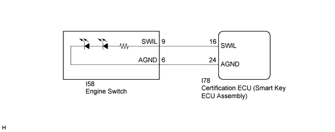
WIRING DIAGRAM
INSPECTION PROCEDURE
PROCEDURE
-
PERFORM ACTIVE TEST USING INTELLIGENT TESTER
-
Connect the intelligent tester to the DLC3.
-
Turn the ignition switch to ON.
-
Turn the intelligent tester on.
-
Enter the following menus: Body / Main Body / Active Test.
-
Check that the illumination operates.
Main Body Tester Display Test Part Control Range Diagnostic Note Illuminated Entry System Engine switch illumination ON/OFF - OK Engine switch illumination comes on.
NG 
INSPECT ENGINE SWITCH Click here
OK 
PROCEED TO NEXT SUSPECTED AREA SHOWN IN PROBLEM SYMPTOMS TABLE Click here
-
-
INSPECT ENGINE SWITCH
-
Remove the engine switch Click here for 2AR-FE, Click here for 2GR-FE, Click here for 6AR-FSE).
-
Inspect the engine switch Click here for 2AR-FE, Click here for 2GR-FE, Click here for 6AR-FSE).
OK Engine switch illumination comes on. Result Result Proceed to OK A NG (for 2AR-FE) B NG (for 2GR-FE) C NG (for 6AR-FSE) D
B 
REPLACE ENGINE SWITCH Click here
C
REPLACE ENGINE SWITCH Click here
D
REPLACE ENGINE SWITCH Click here
A 
-
-
CHECK HARNESS AND CONNECTOR (ENGINE SWITCH - CERTIFICATION ECU (SMART KEY ECU ASSEMBLY))
-
Disconnect the I78 certification ECU (smart key ECU assembly) connector.
-
Disconnect the I58 engine switch connector.
-
Measure the resistance according to the value(s) in the table below.
Standard Resistance Tester Connection Condition Specified Condition I58-9 (SWIL) - I78-16 (SWIL) Always Below 1 Ω I58-6 (AGND) - I78-24 (AGND) Always Below 1 Ω I58-9 (SWIL) - Body ground Always 10 kΩ or higher I58-6 (AGND) - Body ground Always 10 kΩ or higher
NG
REPAIR OR REPLACE HARNESS OR CONNECTOR
OK
REPLACE CERTIFICATION ECU (SMART KEY ECU ASSEMBLY)
-