ENGINE IMMOBILISER SYSTEM (w/ Smart Entry and Start System), Diagnostic DTC:B2799, B279986
| DTC Code | DTC Name |
|---|---|
| B2799 | Engine Immobiliser System Malfunction |
| B279986 | Engine Immobiliser System Signal (Some Circuit Quantity, Reported via Serial Data) Invalid |
DESCRIPTION
-
w/ Entry Function on Driver Door except TMMK Made:
When there are communication malfunctions between the ECM and ID code box (immobiliser code ECU), or when the communication ID codes do not match, the ECM stores this DTC.
-
w/o Entry Function on Driver Door or for TMMK Made:
When there are communication malfunctions between the ECM and certification ECU (smart key ECU assembly), or when the communication ID codes do not match, the ECM stores this DTC.
| DTC Code | DTC Detection Condition | Trouble Area | DTC Output Confirmation Operation |
|---|---|---|---|
| B2799 | Either condition is met (1 trip detection logic*3):
|
|
Either condition is met:
|
-
*1: w/ Entry Function on Driver Door except TMMK Made
-
*2: w/o Entry Function on Driver Door or for TMMK Made
-
*3: Only output while a malfunction is present.
| Vehicle Condition when Malfunction Detected | Fail-safe Operation when Malfunction Detected |
|---|---|
| Engine cannot be started | - |
| DTC Code | Data List and Active Test |
|---|---|
|
- |
-
*1: for 2GR-FE or 2AR-FE
-
*2: for 6AR-FSE
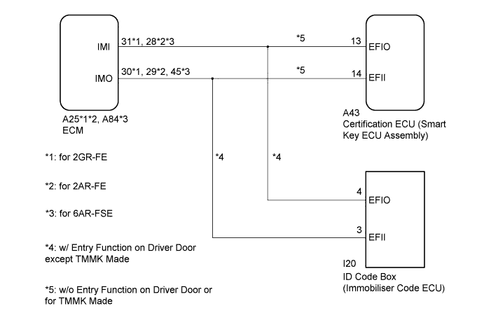
WIRING DIAGRAM
INSPECTION PROCEDURE
Note
-
When replacing the certification ECU (smart key ECU assembly)*1 or ID code box (immobiliser code ECU)*2, refer to Service Bulletin.
-
After performing repairs, perform the operation that fulfills the DTC output confirmation operation, and then confirm that no DTCs are output again.
-
*1: w/o Entry Function on Driver Door or for TMMK Made
-
*2: w/ Entry Function on Driver Door except TMMK Made
Tech Tips
When DTC B2799*1 or B279986*2 and the certification ECU (smart key ECU assembly) DTC are output simultaneously, first perform troubleshooting for the certification ECU (smart key ECU assembly) DTC.
-
*1: for 2GR-FE or 2AR-FE
-
*2: for 6AR-FSE
PROCEDURE
-
REGISTER ECU COMMUNICATION ID
-
Register the ECU communication ID.
Tech Tips
Refer to Service Bulletin.
NEXT 
-
-
CLEAR DTC
-
Clear the DTCs Click here.
NEXT
-
-
CHECK FOR DTC
-
Start the engine.
-
Perform "DTC Output Confirmation Operation" procedure.
-
Check for DTCs Click here.
OK DTC B2799*1 or B279986*2 is not output. Result Result Proceed to OK A NG (DTC B2799*1 or B279986*2 is output) (w/o Entry Function on Driver Door or for TMMK Made) B NG (DTC B2799 is output) (w/ Entry Function on Driver Door except TMMK Made) C NG (Other DTCs are output) D
-
*1: for 2AR-FE
-
*2: for 6AR-FSE
-
B 
CHECK HARNESS AND CONNECTOR (CERTIFICATION ECU (SMART KEY ECU ASSEMBLY) - ECM) Click here
C
REGISTER ECU COMMUNICATION ID Click here
D 
GO TO DIAGNOSTIC TROUBLE CODE CHART Click here
A 
END (COMMUNICATION ID REGISTRATION WAS DEFECTIVE)
-
-
CHECK HARNESS AND CONNECTOR (CERTIFICATION ECU (SMART KEY ECU ASSEMBLY) - ECM)
-
Disconnect the A43 certification ECU (smart key ECU assembly) connector.
-
Disconnect the A25*1 or A84*2 ECM connector.
-
*1: for 2AR-FE
-
*2: for 6AR-FSE
-
-
Measure the resistance according to the value(s) in the table below.
Standard Resistance for 2AR-FE Tester Connection Condition Specified Condition A43-14 (EFII) - A25-29 (IMO) Always Below 1 Ω A43-14 (EFII) or A25-29 (IMO) - Body ground Always 10 kΩ or higher A43-13 (EFIO) - A25-28 (IMI) Always Below 1 Ω A43-13 (EFIO) or A25-28 (IMI) - Body ground Always 10 kΩ or higher for 6AR-FE Tester Connection Condition Specified Condition A43-14 (EFII) - A84-45 (IMO) Always Below 1 Ω A43-14 (EFII) or A84-45 (IMO) - Body ground Always 10 kΩ or higher A43-13 (EFIO) - A84-28 (IMI) Always Below 1 Ω A43-13 (EFIO) or A84-28 (IMI) - Body ground Always 10 kΩ or higher
NG
REPAIR OR REPLACE HARNESS OR CONNECTOR
OK
-
-
INSPECT CERTIFICATION ECU (SMART KEY ECU ASSEMBLY) (TERMINAL EFII)
-
Using an oscilloscope, check the waveform.
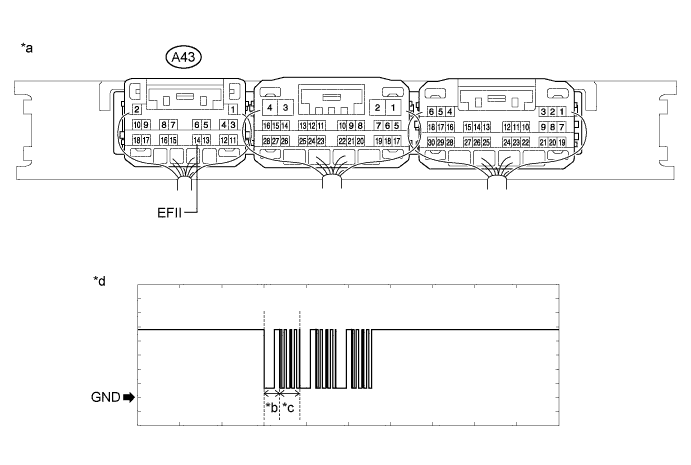
Text in Illustration *a Component with harness connected
(Certification ECU (Smart Key ECU Assembly))
*b Approximately 160 ms *c Approximately 270 ms *d Waveform Measurement Condition Tester Connection Condition Tool Setting Specified Condition A43-14 (EFII) - Body ground Within 3 seconds of engine start or within 3 seconds of engine switch turned on (IG) after battery cable disconnected and reconnected 2 V/DIV., 500 ms./DIV. Pulse generation
(See waveform)
OK The waveform is similar to that shown in the illustration. Result Result Proceed to Normal waveform A Terminal IMO stuck low (2.4 V or less) B Terminal IMO stuck high (12 V), or has abnormal wavelength or shape (for 2AR-FE) C Terminal IMO stuck high (12 V), or has abnormal wavelength or shape (for 6AR-FSE) D
B
INSPECT ECM (IMO TERMINAL VOLTAGE) Click here
C
REPLACE ECM Click here
D
REPLACE ECM Click here
A
-
-
INSPECT CERTIFICATION ECU (SMART KEY ECU ASSEMBLY) (TERMINAL EFIO)
-
Using an oscilloscope, check the waveform.
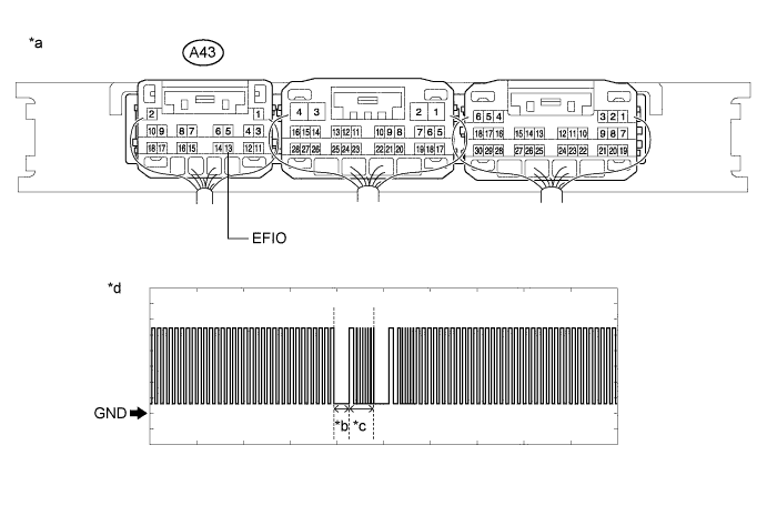
Text in Illustration *a Component with harness connected
(Certification ECU (Smart Key ECU Assembly))
*b Approximately 160 ms *c Approximately 270 ms *d Waveform Measurement Condition Tester Connection Condition Tool Setting Specified Condition A43-13 (EFIO) - Body ground Engine switch on (IG) using registered electrical key transmitter sub-assembly 2 V/DIV., 500 ms./DIV. Pulse generation
(See waveform)
OK The waveform is similar to that shown in the illustration.
NG
REPLACE CERTIFICATION ECU (SMART KEY ECU ASSEMBLY)
OK
-
-
REGISTER ECU COMMUNICATION ID
-
Register the ECU communication ID.
Tech Tips
Refer to Service Bulletin.
NEXT
-
-
CHECK WHETHER ENGINE STARTS
-
Using an electrical key transmitter sub-assembly which is registered to the vehicle, turn the engine switch on (IG).
-
Check that the engine starts 5 seconds after the engine switch was turned on (IG).
OK Engine starts normally. Result Result Proceed to OK A NG (for 2AR-FE) B NG (for 6AR-FSE) C
B
REPLACE ECM Click here
C
REPLACE ECM Click here
A
END (COMMUNICATION ID REGISTRATION WAS DEFECTIVE)
-
-
INSPECT ECM (IMO TERMINAL VOLTAGE)
-
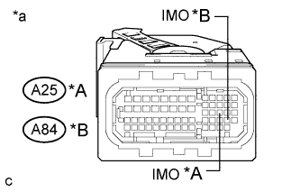
Text in Illustration *A for 2AR-FE *B for 6AR-FSE *a Front view of wire harness connector
(to ECM)
Disconnect the A25*1 or A84*2 ECM connector.
-
*1: for 2AR-FE
-
*2: for 6AR-FSE
-
-
Turn the engine switch on (IG).
-
Measure the voltage according to the value(s) in the table below.
Standard Voltage for 2AR-FE Tester Connection Condition Specified Condition A25-29 (IMO) - Body ground Engine switch on (IG) using registered electrical key transmitter sub-assembly Terminal IMO stuck low (2.4 V or less) Terminal IMO stuck high (12 V) or abnormal waveform for 6AR-FSE Tester Connection Condition Specified Condition A84-45 (IMO) - Body ground Engine switch on (IG) using registered electrical key transmitter sub-assembly Terminal IMO stuck low (2.4 V or less) Terminal IMO stuck high (12 V) or abnormal waveform Result Result Proceed to Terminal IMO stuck low (2.4 V or less) A Terminal IMO stuck high (12 V) or abnormal waveform (for 2AR-FE) B Terminal IMO stuck high (12 V) or abnormal waveform (for 6AR-FSE) C
B
REPLACE ECM Click here
C
REPLACE ECM Click here
A
-
-
REPLACE CERTIFICATION ECU (SMART KEY ECU ASSEMBLY)
-
Replace the certification ECU (smart key ECU assembly) with a new one.
Tech Tips
Refer to Service Bulletin.
NEXT
-
-
REGISTER ECU COMMUNICATION ID
-
Register the ECU communication ID.
Tech Tips
Refer to Service Bulletin.
NEXT
-
-
CHECK WHETHER ENGINE STARTS
-
Using an electrical key transmitter sub-assembly which is registered to the vehicle, turn the engine switch on (IG).
-
Check that the engine starts 5 seconds after the engine switch was turned on (IG).
OK Engine starts normally. Result Result Proceed to OK A NG (for 2AR-FE) B NG (for 6AR-FSE) C
B
REPLACE ECM Click here
C
REPLACE ECM Click here
A
END (CERTIFICATION ECU (SMART KEY ECU ASSEMBLY) WAS DEFECTIVE)
-
-
REGISTER ECU COMMUNICATION ID
Register the ECU communication ID.
Tech Tips
Refer to Service Bulletin.
NEXT
-
CLEAR DTC
-
Clear the DTCs Click here.
NEXT
-
-
CHECK FOR DTC
-
Perform "DTC Output Confirmation Operation" procedure.
-
Check for DTCs Click here.
OK DTC B2799 is not output.
NG
CHECK HARNESS AND CONNECTOR (ID CODE BOX (IMMOBILISER CODE ECU) - ECM) Click here
OK
END (COMMUNICATION ID REGISTRATION WAS DEFECTIVE)
-
-
CHECK HARNESS AND CONNECTOR (ID CODE BOX (IMMOBILISER CODE ECU) - ECM)
-
Disconnect the I20 ID code box (immobiliser code ECU) connector.
-
Disconnect the A25 ECM connector.
-
Measure the resistance according to the value(s) in the table below.
Standard Resistance for 2GR-FE Tester Connection Condition Specified Condition I20-3 (EFII) - A25-30 (IMO) Always Below 1 Ω I20-3 (EFII) or A25-30 (IMO) - Body ground Always 10 kΩ or higher I20-4 (EFIO) - A25-31 (IMI) Always Below 1 Ω I20-4 (EFIO) or A25-31 (IMI) - Body ground Always 10 kΩ or higher for 2AR-FE Tester Connection Condition Specified Condition I20-3 (EFII) - A25-29 (IMO) Always Below 1 Ω I20-3 (EFII) or A25-29 (IMO) - Body ground Always 10 kΩ or higher I20-4 (EFIO) - A25-28 (IMI) Always Below 1 Ω I20-4 (EFIO) or A25-28 (IMI) - Body ground Always 10 kΩ or higher
NG
REPAIR OR REPLACE HARNESS OR CONNECTOR
OK
-
-
REPLACE ECM
-
Temporarily replace the ECM with a new one Click here for 2GR-FE , Click here for 2AR-FE).
NEXT
-
-
CLEAR DTC
-
Clear the DTCs Click here.
NEXT
-
-
CHECK FOR DTC
-
Perform "DTC Output Confirmation Operation" procedure.
-
Check for DTCs Click here.
OK DTC B2799 is not output.
NG
REPLACE ID CODE BOX (IMMOBILISER CODE ECU)
OK
END (ECM WAS DEFECTIVE)
-