ENGINE IMMOBILISER SYSTEM (w/ Smart Entry and Start System), Diagnostic DTC:B2784
| DTC Code | DTC Name |
|---|---|
| B2784 | Antenna Coil Open / Short |
DESCRIPTION
When an open or short circuit is detected in the transponder key amplifier coil built into the engine switch, the certification ECU (smart key ECU assembly) stores this DTC. This DTC is also stored as a past DTC.
| DTC Code | DTC Detection Condition | Trouble Area | DTC Output Confirmation Operation |
|---|---|---|---|
| B2784 | The transponder key amplifier coil built into the engine switch is open (see below) or shorted (determined by communication with certification ECU (smart key ECU assembly)) (1 trip detection logic*).
|
|
With the shift lever in P, the key held near the engine switch and an engine start operation is performed by pressing and holding the engine switch when the key battery is depleted. |
-
*: Only output while a malfunction is present.
| Vehicle Condition when Malfunction Detected | Fail-safe Operation when Malfunction Detected |
|---|---|
| Engine cannot be started when key battery is depleted by holding key near engine switch and pressing and holding engine switch with shift lever in P | - |
| DTC Code | Data List and Active Test |
|---|---|
| B2784 | - |
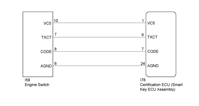
WIRING DIAGRAM
INSPECTION PROCEDURE
Note
-
Before replacing the certification ECU (smart key ECU assembly), refer to Service Bulletin.
-
After performing repairs, perform the operation that fulfills the DTC output confirmation operation, and then confirm that no DTCs are output again.
PROCEDURE
-
CLEAR DTC
-
Clear the DTCs Click here.
NEXT 
-
-
CHECK DTC OUTPUT
-
Perform "DTC Output Confirmation Operation" procedure.
-
Check for DTCs Click here.
OK DTC B2784 is not output.
NG 
CHECK ENGINE SWITCH (OUTPUT) Click here
OK 
USE SIMULATION METHOD TO CHECK Click here
-
-
CHECK ENGINE SWITCH (OUTPUT)
-
Using an oscilloscope, check the waveform.
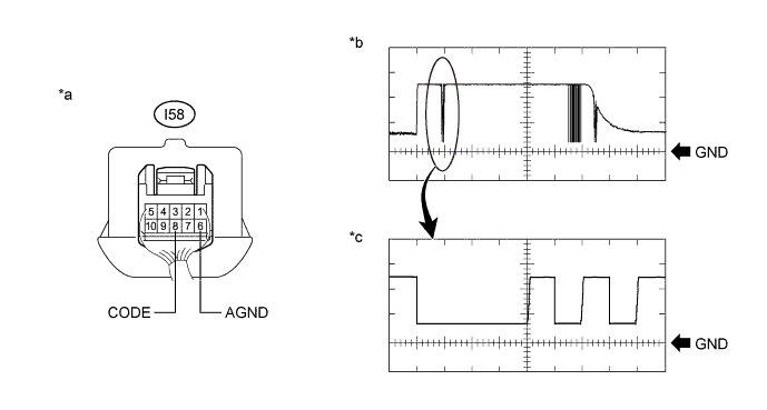
Text in Illustration *a Component with harness connected
(Engine Switch)
*b Waveform *c Waveform (detail) - - Measurement Condition Tester Connection Condition Tool Setting Specified Condition I58-8 (CODE) - I58-6 (AGND) Engine switch off, engine switch pressed with key held near engine switch* 1 V/DIV., 20 ms./DIV. Pulse generation
(See waveform)
2 V/DIV., 100 μs./DIV. Pulse generation
(See waveform (detail))
-
*: Remove the key battery before performing this inspection.
OK The waveform is similar to that shown in the illustration Result Result Proceed to OK A NG (for 2GR-FE) B NG (for 2AR-FE) C NG (for 6AR-FSE) D -
B 
REPLACE ENGINE SWITCH Click here
C
REPLACE ENGINE SWITCH Click here
D
REPLACE ENGINE SWITCH Click here
A
-
-
REPLACE CERTIFICATION ECU (SMART KEY ECU ASSEMBLY)
-
Replace the certification ECU (smart key ECU assembly) with a new one.
Tech Tips
Refer to Service Bulletin.
NEXT
-
-
REGISTER ECU COMMUNICATION ID
-
Register the ECU communication ID.
Tech Tips
Refer to Service Bulletin.
NEXT
-
-
CLEAR DTC
-
Clear the DTCs Click here.
NEXT
-
-
CHECK FOR DTC
-
Perform "DTC Output Confirmation Operation" procedure.
-
Check for DTCs Click here.
OK DTC B2784 is not output. Result Result Proceed to OK A NG (for 2GR-FE) B NG (for 2AR-FE) C NG (for 6AR-FSE) D
B
REPLACE ENGINE SWITCH Click here
C
REPLACE ENGINE SWITCH Click here
D
REPLACE ENGINE SWITCH Click here
A
END (CERTIFICATION ECU (SMART KEY ECU ASSEMBLY) WAS DEFECTIVE)
-