SMART ENTRY AND START SYSTEM (for Entry Function) Luggage Compartment Door Entry Unlock Function does not Operate when Key is Outside Luggage Compartment
DESCRIPTION
If the luggage compartment door entry unlock function does not operate, the request code may not be being transmitted from the luggage compartment door. If the entry functions for other doors operate properly, communication between the electrical key transmitter sub-assembly and door control receiver is normal. In this case, there may be a problem with request code transmission (communication between the certification ECU (smart key ECU assembly) and electrical key antenna (outside luggage)), a luggage compartment door outer switch malfunction or wave interference.
Tech Tips
If the cause of the malfunction is stored in the certification ECU (smart key ECU assembly), the following table is helpful in checking whether or not the malfunction was caused by wave interference.
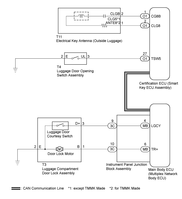
WIRING DIAGRAM
INSPECTION PROCEDURE
Note
-
The smart entry and start system (for Entry Function) uses the CAN communication system and LIN communication system. First inspect the communication systems by following How to Proceed with Troubleshooting Click here. Troubleshoot the smart entry and start system (for Entry Function) after confirming that the communication systems are functioning properly.
-
When using the intelligent tester with the engine switch off to troubleshoot:
Connect the intelligent tester to the DLC3 and turn a courtesy light switch on and off at 1.5-second intervals until communication between the intelligent tester and vehicle begins.
-
Check that there are no electrical key transmitter sub-assemblies in the vehicle.
-
Before performing the inspection, check that DTC B1242 (wireless door lock control) is not output Click here.
-
Before replacing the certification ECU (smart key ECU assembly), refer to the smart entry and start system (for Entry Function) precaution Click here.
-
After repair, confirm that no DTCs are output by performing the "DTC Output Confirmation Operation".
PROCEDURE
-
READ VALUE USING INTELLIGENT TESTER (LUGGAGE COMPARTMENT DOOR OPEN MODE)
-
Connect the intelligent tester to the DLC3.
-
Turn the engine switch on (IG).
-
Turn the intelligent tester on.
-
Enter the following menus: Body / Entry & Start / Data List.
-
Read the Data List according to the display on the intelligent tester.
Entry & Start Tester Display Measurement Item/Range Normal Condition Diagnostic Note Trunk Open Mode Luggage door opening switch assembly / ON or OFF Customization status displayed - Result Result Proceed to Entry luggage compartment door open mode is ON A Entry luggage compartment door open mode is OFF B
B 
PERFORM CUSTOMIZE SETTING (Proceed to Customize Parameters) Click here
A 
-
-
READ VALUE USING INTELLIGENT TESTER (LUGGAGE DOOR OPENING SWITCH ASSEMBLY)
-
Connect the intelligent tester to the DLC3.
-
Turn the engine switch on (IG).
-
Turn the intelligent tester on.
-
Enter the following menus: Body / Entry & Start / Data List.
-
Read the Data List according to the display on the intelligent tester.
Entry & Start Tester Display Measurement Item/Range Normal Condition Diagnostic Note Tr/B-Door Unlock SW Luggage compartment door opener outer switch / ON or OFF ON: Luggage compartment door opener outer switch pushed
OFF: Luggage compartment door opener outer switch not pushed
- OK On the intelligent tester screen, the display changes between ON and OFF according to the chart above.
NG 
INSPECT LUGGAGE DOOR OPENING SWITCH ASSEMBLY Click here
OK
-
-
PERFORM ACTIVE TEST USING ACTIVE TEST USING INTELLIGENT TESTER
-
Connect the intelligent tester to the DLC3.
-
Turn the engine switch on (IG).
-
Turn the intelligent tester on.
-
Enter the following menus: Body / Main Body / Active Test.
-
Read the Data List according to the display on the intelligent tester.
Main Body Tester Display Test Part Control Range Diagnostic Note Trunk and Back-door Open Operate luggage compartment door lock motor ON/OFF - OK Luggage compartment door lock motor operates.
NG
INSPECT LUGGAGE COMPARTMENT DOOR LOCK ASSEMBLY Click here
OK
-
-
CHECK WAVE ENVIRONMENT
-
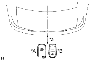
Text in Illustration *A for Type A *B for Type B *a Approximately 0.3 m (0.984 ft.) Bring the electrical key transmitter sub-assembly near the electrical key antenna (outside luggage), and perform an entry luggage compartment open function check.
Note
If the electrical key transmitter sub-assembly is brought within 0.2 m (0.656 ft.) of the rear bumper, communication is not possible.
Tech Tips
-
When pressing the luggage compartment door opener outer switch, hold the electrical key transmitter sub-assembly approximately 1 m (3.28 ft.) above the ground and approximately 0.3 m (0.984 ft.) away from the vehicle as shown in the illustration.
-
When the electrical key transmitter sub-assembly is brought near the electrical key antenna (outside luggage), the possibility of wave interference decreases, and it can be determined if wave interference is causing the problem symptom.
-
If the operation check is normal, the possibility of wave interference is high. Also, added vehicle components may cause wave interference. If installed, remove them and perform the operation check.
OK Entry functions operate normally. -
NG
CHECK KEY DIAGNOSTIC MODE Click here
OK 
AFFECTED BY WAVE INTERFERENCE
-
-
CHECK KEY DIAGNOSTIC MODE
-
Check the following antennas in the key diagnostic mode Click here.
-
Text in Illustration *A for Type A *B for Type B *a 0.7 to 1.0 m (2.30 to 3.28 ft.) Select either channel 1 or channel 2 and inspect the key diagnostic mode for each channel.
-
When the electrical key transmitter sub-assembly is held at the same height as the rear bumper upper surface, align it with the center of the rear of the vehicle and check that the wireless door lock buzzer sounds.
Tech Tips
-
Hold the electrical key transmitter sub-assembly at the same height as the rear bumper upper surface and align it with the center of the rear of the vehicle (0.7 to 1.0 m (2.30 to 3.28 ft.)). Make sure that the direction of the electrical key transmitter sub-assembly is as shown in the illustration.
-
If the buzzer sounds, it can be determined that the luggage compartment exterior transmitter is operating normally.
-
If the buzzer sounds with [CH1] displayed but not with [CH2], the electrical key transmitter sub-assembly cannot be detected by channel 2 due to a malfunction, such as wave interference.
OK Wireless door lock buzzer sounds. -
-
NG
CHECK HARNESS AND CONNECTOR (CERTIFICATION ECU - ELECTRICAL KEY ANTENNA) Click here
OK
REPLACE CERTIFICATION ECU (SMART KEY ECU ASSEMBLY)
-
-
CHECK HARNESS AND CONNECTOR (CERTIFICATION ECU - ELECTRICAL KEY ANTENNA)
-
Disconnect the O1 certification ECU (smart key ECU assembly) connector.
-
Disconnect the T11 electrical key antenna (outside luggage) connector.
-
Measure the resistance according to the value(s) in the table below.
Standard Resistance except TMMK Made Tester Connection Condition Specified Condition O1-1 (CG8B) - T11-2 (CLGB) Always Below 1 Ω O1-2 (CLG8) - T11-1 (CLG5) Always Below 1 Ω O1-1 (CG8B) or T11-2 (CLGB) - Body ground Always 10 kΩ or higher O1-2 (CLG8) or T11-1 (CLG5) - Body ground Always 10 kΩ or higher for TMMK Made Tester Connection Condition Specified Condition O1-1 (CG8B) - T11-2 (CLGB) Always Below 1 Ω O1-2 (CLG8) - T11-1 (ANTE8) Always Below 1 Ω O1-1 (CG8B) or T11-2 (CLGB) - Body ground Always 10 kΩ or higher O1-2 (CLG8) or T11-1 (ANTE8) - Body ground Always 10 kΩ or higher
NG
REPAIR OR REPLACE HARNESS OR CONNECTOR
OK
-
-
INSPECT ELECTRICAL KEY ANTENNA (OUTSIDE LUGGAGE)
-
Remove the outside electrical key antenna (outside luggage) Click here.
-
Inspect the outside electrical key antenna (outside luggage) Click here.
NG
REPLACE ELECTRICAL KEY ANTENNA (OUTSIDE LUGGAGE) Click here
OK
REPLACE CERTIFICATION ECU (SMART KEY ECU ASSEMBLY)
-
-
INSPECT LUGGAGE DOOR OPENING SWITCH ASSEMBLY
-
Remove the luggage door opening switch assembly Click here.
-
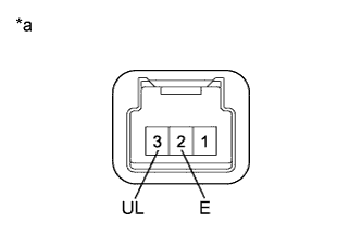
Text in Illustration *a Component without harness connected
(Luggage Door Opening Switch Assembly)
Measure the resistance according to the value(s) in the table below.
Standard Resistance Tester Connection Switch Condition Specified Condition 2 (E) - 3 (UL) Luggage door opening switch assembly not pushed 10 kΩ or higher 2 (E) - 3 (UL) Luggage door opening switch assembly pushed Below 1 Ω
NG
REPLACE LUGGAGE DOOR OPENING SWITCH ASSEMBLY Click here
OK
-
-
CHECK HARNESS AND CONNECTOR (CERTIFICATION ECU - OPENING SWITCH)
-
Disconnect the O1 certification ECU (smart key ECU assembly) connector.
-
Disconnect the T4 luggage door opening switch assembly connector.
-
Measure the resistance according to the value(s) in the table below.
Standard Resistance Tester Connection Condition Specified Condition O1-27 (TSW5) - T4-3 (UL) Always Below 1 Ω O1-27 (TSW5) or T4-3 (UL) - Body ground Always 10 kΩ or higher T4-2 (E) - Body ground Always Below 1 Ω
NG
REPAIR OR REPLACE HARNESS OR CONNECTOR
OK
REPLACE CERTIFICATION ECU (SMART KEY ECU ASSEMBLY)
-
-
INSPECT LUGGAGE COMPARTMENT DOOR LOCK ASSEMBLY
-
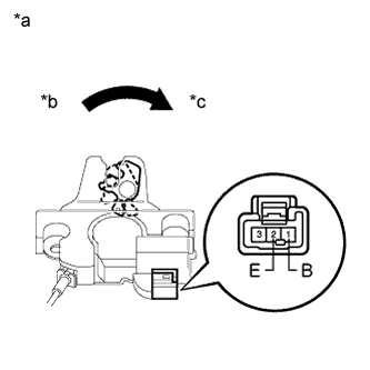
Text in Illustration *a Component without harness connected:
(Luggage Compartment Door Lock Assembly)
*b Close (Lock) *c Open (Unlock) Remove the luggage compartment door lock assembly Click here.
-
Check the operation of the door lock motor.
-
Move the door lock to the close (lock) position.
-
Apply battery voltage to the door lock motor and check the operation of the door lock motor.
OK Measurement Condition Specified Condition Battery positive (+) → 1 (B)
Battery negative (-) → 2 (E)
Luggage compartment door lock motor open (unlock) operation
-
-
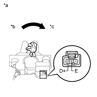
Text in Illustration *a Component without harness connected
(Luggage Compartment Door Lock Assembly)
*b Close (Lock) *c Open (Unlock) Check the door courtesy light switch.
-
Move the door lock to the close (lock) position.
-
Measure the resistance according to the value(s) in the table below.
Standard Resistance Measurement Condition Door Lock Condition Specified Condition 2 (E) - 3 (D+) Close (Lock) 10 kΩ or higher 2 (E) - 3 (D+) Open (Unlock) Below 1 Ω
-
NG
REPLACE LUGGAGE COMPARTMENT DOOR LOCK ASSEMBLY Click here
OK
-
-
CHECK HARNESS AND CONNECTOR (LUGGAGE DOOR LOCK - INSTRUMENT PANEL JUNCTION BLOCK)
-
Luggage compartment door lock motor:
-
Disconnect the 3C instrument panel junction block assembly connector.
-
Disconnect the T3 luggage compartment door lock assembly connector.
-
Measure the resistance according to the value(s) in the table below.
Standard Resistance Tester Connection Condition Specified Condition T3-2 (E) - Body ground Always Below 1 Ω 3C-10 (TR+) or T3-1 (B) - Body ground Always 10 kΩ or higher 3C-10 (TR+) - T3-1 (B) Always Below 1 Ω
-
-
Luggage door courtesy light switch:
-
Disconnect the 3C instrument panel junction block assembly connector.
-
Disconnect the T3 luggage compartment door lock assembly connector.
-
Measure the resistance according to the value(s) in the table below.
Standard Resistance Tester Connection Condition Specified Condition T3-2 (E) - Body ground Always Below 1 Ω 3C-9 (LGCY) or T3-3 (D+) - Body ground Always 10 kΩ or higher 3C-9 (LGCY) - T3-3 (D+) Always Below 1 Ω
-
NG
REPAIR OR REPLACE HARNESS OR CONNECTOR
OK
-
-
REPLACE INSTRUMENT PANEL JUNCTION BLOCK ASSEMBLY
-
Temporarily replace the instrument panel junction block assembly with a new one Click here.
NEXT
-
-
CHECK OPERATION
-
Check that the luggage compartment door entry unlock functions operate normally Click here.
OK Luggage compartment door entry unlock functions operate normally.
NG
REPLACE MAIN BODY ECU (MULTIPLEX NETWORK BODY ECU) Click here
OK
END (INSTRUMENT PANEL JUNCTION BLOCK ASSEMBLY WAS DEFECTIVE)
-