UNLOCK WARNING SWITCH REMOVAL
-
PRECAUTION
Note
After turning the ignition switch off, waiting time may be required before disconnecting the cable from the negative (-) battery terminal. Therefore, make sure to read the disconnecting the cable from the negative (-) battery terminal notices before proceeding with work Click here.
-
ALIGN FRONT WHEELS FACING STRAIGHT AHEAD
-
DISCONNECT CABLE FROM NEGATIVE BATTERY TERMINAL
Note
When disconnecting the cable, some systems need to be initialized after the cable is reconnected Click here.
-
REMOVE LOWER STEERING COLUMN COVER
Note
Removing the lower steering column cover in the incorrect order will cause the parts to break.
-
Release the tilt and telescopic lever, and fully extend and lower the steering column assembly.
-
Lock the tilt and telescopic lever.
-
Turn the steering wheel assembly to the left and remove the screw.
-
Turn the steering wheel assembly to the right and remove the screw.
-
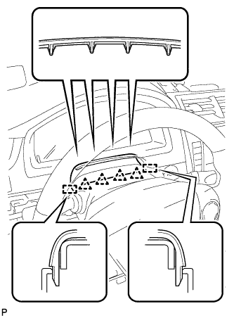
Push the right and left sides of the lower steering column cover to disengage the 2 claws.
-
Insert your fingers into the opening of the tilt lever of the lower steering column cover to disengage the 2 claws.
Tech Tips
Spread the claws to disengage them.
-
-
REMOVE UPPER STEERING COLUMN COVER
-
Disengage the 4 clips and 2 guides to separate the instrument cluster finish panel assembly from the upper steering column cover.
-
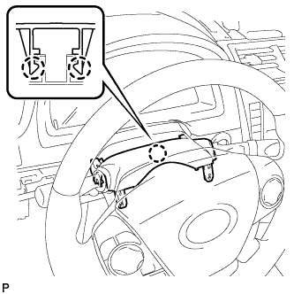
Disengage the 2 claws and remove the upper steering column cover.
-
-
REMOVE TRANSPONDER KEY COIL
-
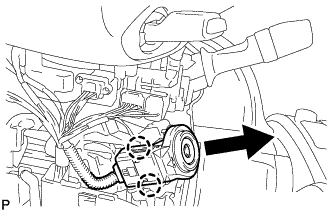
Disengage the 2 claws and disconnect the transponder key coil.
-
Disconnect the connector to remove the transponder key coil.
-
-
REMOVE IGNITION SWITCH LOCK CYLINDER ASSEMBLY
-
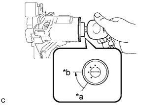
Text in Illustration *a LOCK *b ACC Turn the ignition switch lock cylinder assembly to the ACC position.
-
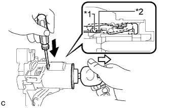
Text in Illustration *1 Claw *2 Stopper 
Push 
Pull Insert a screwdriver into the hole of the steering column upper bracket assembly as shown in the illustration. Pull the ignition switch lock cylinder assembly until its claw contacts the stopper of the steering column upper bracket assembly.
Note
Make sure to pull the ignition switch lock cylinder assembly until its claw contacts the stopper of the steering column upper bracket assembly. Failure to do so will affect later work operations.
-
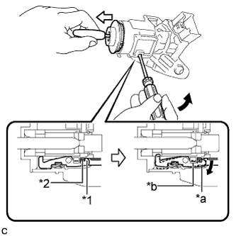
Text in Illustration *1 Claw *2 Stopper *a Claw disengaged *b Driver Insertion Hole Tilt Pull out Insert a screwdriver into the hole of the steering column upper bracket assembly. Tilt the screwdriver as shown in the illustration to disengage the claw of the ignition switch lock cylinder assembly, and pull out the ignition switch lock cylinder assembly from the steering column upper bracket assembly.
-
-
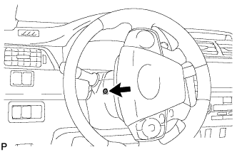
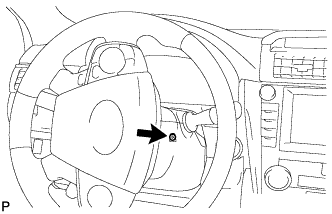
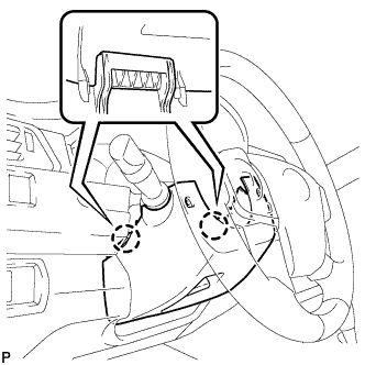
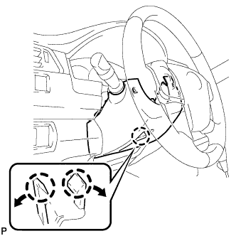
REMOVE UNLOCK WARNING SWITCH ASSEMBLY
-
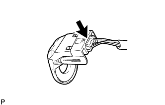
Disconnect the connector.
-
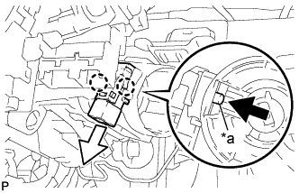
Text in Illustration *a Center Part Remove the unlock warning switch assembly by pushing up the center part and releasing the 2 claws.
Tech Tips
Slide the unlock warning switch assembly in the direction shown by the arrow in the illustration to remove it.
-