LIN COMMUNICATION SYSTEM TERMINALS OF ECU
-
CHECK MAIN BODY ECU (MULTIPLEX NETWORK BODY ECU)
-
Disconnect the 3D and 3B instrument panel junction block assembly connectors.
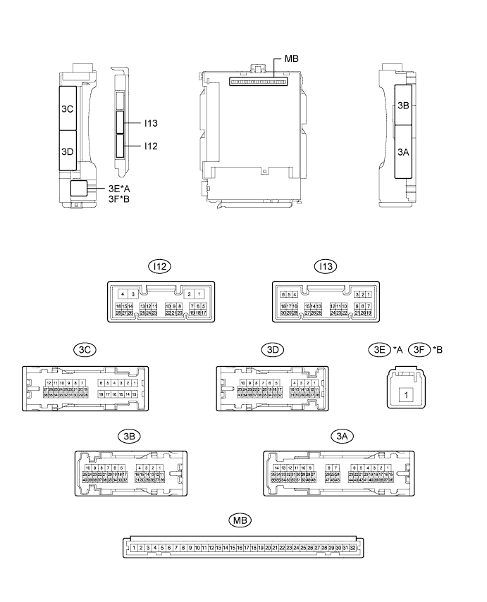
Text in Illustration *A for LHD *B for RHD -
Measure the voltage and resistance according to the value(s) in the table below.
Tech Tips
Measure the values on the wire harness side with the connectors disconnected.
Terminal No. (Symbol) Wiring Color Terminal Description Condition Specified Condition 3D-31 (BECU) - Body ground V - Body ground Battery power supply Always 11 to 14 V 3B-7 (GND1) - Body ground W-B - Body ground Ground Always Below 1 Ω -
Reconnect the 3D and 3B instrument panel junction block assembly connectors.
-
Check for pulses according to the value(s) in the table below.
Terminal No. (Symbol) Wiring Color Terminal Description Condition Specified Condition 3C-26 (LIN2) - 3B-7 (GND1)* P - W-B LIN communication line Ignition switch ON Pulse generation 3B-30 (LIN2) - 3B-7 (GND1) P - W-B LIN communication line Ignition switch ON Pulse generation
-
*: w/ Jam Protection Function on 4 Windows
-
-
-
CHECK POWER WINDOW REGULATOR MOTOR ASSEMBLY (for Driver Door)
-
Disconnect the K9*1 or J9*2 power window regulator motor assembly (for driver door) connector.
-
*1: for LHD
-
*2: for RHD

Text in Illustration *A for LHD *B for RHD -
-
Measure the voltage and resistance according to the value(s) in the table below.
Tech Tips
Measure the values on the wire harness side with the connector disconnected.
for LHD Terminal No. (Symbol) Wiring Color Terminal Description Condition Specified Condition K9-2 (B) - K9-1 (GND) GR*1 - W-B
W*2 - W-B
Battery power supply Always 11 to 14 V K9-1 (GND) - Body ground W-B - Body ground Ground Always Below 1 Ω
-
*1: except TMMK Made
*2: for TMMK Made
for RHD Terminal No. (Symbol) Wiring Color Terminal Description Condition Specified Condition J9-2 (B) - J9-1 (GND) GR - W-B Battery power supply Always 11 to 14 V J9-1 (GND) - Body ground W-B - Body ground Ground Always Below 1 Ω -
-
Reconnect the K9*1 or J9*2 power window regulator motor assembly (for driver door) connector.
-
*1: for LHD
-
*2: for RHD
-
-
Check for pulses according to the value(s) in the table below.
for LHD Terminal No. (Symbol) Wiring Color Terminal Description Condition Specified Condition K9-9 (LIN) - K9-1 (GND) P - W-B LIN communication line Ignition switch ON Pulse generation for RHD Terminal No. (Symbol) Wiring Color Terminal Description Condition Specified Condition J9-9 (LIN) - J9-1 (GND) L - W-B LIN communication line Ignition switch ON Pulse generation
-
-
CHECK POWER WINDOW REGULATOR MOTOR ASSEMBLY (for Front Passenger Door)
-
Disconnect the J9*1 or K9*2 power window regulator motor assembly (for front passenger door) connector.
-
*1: for LHD
-
*2: for RHD

Text in Illustration *A for LHD *B for RHD -
-
Measure the voltage and resistance according to the value(s) in the table below.
Tech Tips
Measure the values on the wire harness side with the connector disconnected.
for LHD Terminal No. (Symbol) Wiring Color Terminal Description Condition Specified Condition J9-2 (B) - J9-1 (GND) GR - W-B Battery power supply Always 11 to 14 V J9-1 (GND) - Body ground W-B - Body ground Ground Always Below 1 Ω for RHD Terminal No. (Symbol) Wiring Color Terminal Description Condition Specified Condition K9-2 (B) - K9-1 (GND) GR - W-B Battery power supply Always 11 to 14 V K9-1 (GND) - Body ground W-B - Body ground Ground Always Below 1 Ω -
Reconnect the J9*1 or K9*2 power window regulator motor assembly (for front passenger door) connector.
-
*1: for LHD
-
*2: for RHD
-
-
Check for pulses according to the value(s) in the table below.
for LHD Terminal No. (Symbol) Wiring Color Terminal Description Condition Specified Condition J9-9 (LIN) - J9-1 (GND) P - W-B LIN communication line Ignition switch ON Pulse generation for RHD Terminal No. (Symbol) Wiring Color Terminal Description Condition Specified Condition K9-9 (LIN) - K9-1 (GND) P - W-B LIN communication line Ignition switch ON Pulse generation
-
-
CHECK POWER WINDOW REGULATOR MOTOR ASSEMBLY (for Rear RH Door) (w/ Jam Protection Function on 4 Windows)
-
Disconnect the L2 power window regulator motor assembly (for rear RH door) connector.

-
Measure the voltage and resistance according to the value(s) in the table below.
Tech Tips
Measure the values on the wire harness side with the connector disconnected.
Terminal No. (Symbol) Wiring Color Terminal Description Condition Specified Condition L2-2 (B) - L2-1 (GND) G - W-B Battery power supply Always 11 to 14 V L2-1 (GND) - Body ground W-B - Body ground Ground Always Below 1 Ω -
Reconnect the L2 power window regulator motor assembly (for rear RH door) connector.
-
Check for pulses according to the value(s) in the table below.
Terminal No. (Symbol) Wiring Color Terminal Description Condition Specified Condition L2-9 (LIN) - L2-1 (GND) P - W-B LIN communication line Ignition switch ON Pulse generation
-
-
CHECK POWER WINDOW REGULATOR MOTOR ASSEMBLY (for Rear LH Door) (w/ Jam Protection Function on 4 Windows)
-
Disconnect the M2 power window regulator motor assembly (for rear LH door) connector.

-
Measure the voltage and resistance according to the value(s) in the table below.
Tech Tips
Measure the values on the wire harness side with the connector disconnected.
Terminal No. (Symbol) Wiring Color Terminal Description Condition Specified Condition M2-2 (B) - M2-1 (GND) G - W-B Battery power supply Always 11 to 14 V M2-1 (GND) - Body ground W-B - Body ground Ground Always Below 1 Ω -
Reconnect the M2 power window regulator motor assembly (for rear LH door) connector.
-
Check for pulses according to the value(s) in the table below.
Terminal No. (Symbol) Wiring Color Terminal Description Condition Specified Condition M2-9 (LIN) - M2-1 (GND) P - W-B LIN communication line Ignition switch ON Pulse generation
-
-
CHECK MULTIPLEX NETWORK MASTER SWITCH ASSEMBLY (w/ Jam Protection Function on 4 Windows)
-
Disconnect the K3*1 or J3*2 multiplex network master switch assembly connector.
-
*1: for LHD
-
*2: for RHD

Text in Illustration *A for LHD *B for RHD -
-
Measure the voltage and resistance according to the value(s) in the table below.
Tech Tips
Measure the values on the wire harness side with the connector disconnected.
for LHD Terminal No. (Symbol) Wiring Color Terminal Description Condition Specified Condition K3-11 (B) - K3-12 (GND) W - BR Battery power supply Always 11 to 14 V K3-12 (GND) - Body ground BR - Body ground Ground Always Below 1 Ω for RHD Terminal No. (Symbol) Wiring Color Terminal Description Condition Specified Condition J3-11 (B) - J3-12 (GND) W - BR Battery power supply Always 11 to 14 V J3-12 (GND) - Body ground BR - Body ground Ground Always Below 1 Ω -
Reconnect the K3*1 or J3*2 multiplex network master switch assembly connector.
-
*1: for LHD
-
*2: for RHD
-
-
Check for pulses according to the value(s) in the table below.
for LHD Terminal No. (Symbol) Wiring Color Terminal Description Condition Specified Condition K3-17 (LIN1) - K3-12 (GND) P - BR LIN communication line Ignition switch ON Pulse generation for RHD Terminal No. (Symbol) Wiring Color Terminal Description Condition Specified Condition J3-17 (LIN1) - J3-12 (GND) P - BR LIN communication line Ignition switch ON Pulse generation
-
-
CHECK POWER WINDOW REGULATOR MASTER SWITCH ASSEMBLY (w/ Jam Protection Function on Front Door Windows)
-
Disconnect the K15 power window regulator master switch assembly connector.

-
Measure the voltage and resistance according to the value(s) in the table below.
Tech Tips
Measure the values on the wire harness side with the connector disconnected.
Terminal No. (Symbol) Wiring Color Terminal Description Condition Specified Condition K15-3 (B) - K15-1 (GND) R - W-B Battery power supply Always 11 to 14 V K15-1 (GND) - Body ground W-B - Body ground Ground Always Below 1 Ω -
Reconnect the K15 power window regulator master switch assembly connector.
-
Check for pulses according to the value(s) in the table below.
Terminal No. (Symbol) Wiring Color Terminal Description Condition Specified Condition K15-6 (LIN1) - K15-1 (GND) P - W-B LIN communication line Ignition switch ON Pulse generation
-
-
CHECK SLIDING ROOF ECU (SLIDING ROOF DRIVE GEAR SUB-ASSEMBLY) (w/ Sliding Roof System)
-
Disconnect the S4 sliding roof ECU (sliding roof drive gear sub-assembly) connector.

-
Measure the voltage and resistance according to the value(s) in the table below.
Tech Tips
Measure the values on the wire harness side with the connector disconnected.
Terminal No. (Symbol) Wiring Color Terminal Description Condition Specified Condition S4-8 (B) - S4-12 (E) B - W-B Battery power supply Always 11 to 14 V S4-12 (E) - Body ground W-B - Body ground Ground Always Below 1 Ω -
Reconnect the S4 sliding roof ECU (sliding roof drive gear sub-assembly) connector.
-
Check for pulses according to the value(s) in the table below.
Terminal No. (Symbol) Wiring Color Terminal Description Condition Specified Condition S4-11 (MPX1) - S4-12 (E) P - W-B LIN communication line Ignition switch ON Pulse generation
-
-
CHECK CERTIFICATION ECU (SMART KEY ECU ASSEMBLY) (w/ Smart Entry and Start System)
-
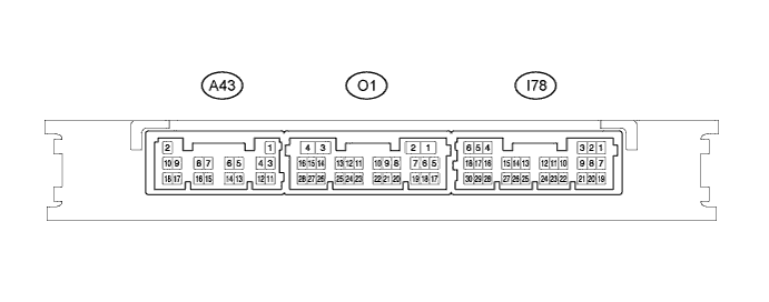
Disconnect the A43 certification ECU (smart key ECU assembly) connector.
-
Measure the voltage and resistance according to the value(s) in the table below.
Tech Tips
Measure the values on the wire harness side with the connector disconnected.
Terminal No. (Symbol) Wiring Color Terminal Description Condition Specified Condition A43-2 (+B) - A43-11 (E) W - W Battery power supply Always 11 to 14 V A43-11 (E) - Body ground W - Body ground Ground Always Below 1 Ω -
Reconnect the A43 certification ECU (smart key ECU assembly) connector.
-
Measure the voltage according to the value(s) in the table below.
-
Check for pulses according to the value(s) in the table below.
Terminal No. (Symbol) Wiring Color Terminal Description Condition Specified Condition I78-5 (IG) - A43-11 (E) LG - W IG power supply Ignition switch ON 11 to 14 V I78-5 (IG) - A43-11 (E) LG - W IG power supply Ignition switch off Below 1 V I78-17 (LIN) - A43-11 (E) Y*1 - W LIN communication line Ignition switch ON Pulse generation V*2 - W LIN communication line Ignition switch ON Pulse generation
-
*1: w/ Entry Function on Driver Door except TMMK Made
-
*2: w/o Entry Function on Driver Door or for TMMK Made
-
-
-
CHECK STEERING LOCK ECU (STEERING LOCK ACTUATOR ASSEMBLY) (w/ Smart Entry and Start System)
-
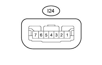
Disconnect the I24 steering lock ECU (steering lock actuator assembly) connector.
-
Measure the resistance and voltage according to the value(s) in the table below.
Terminal No. (Symbol) Wiring Color Terminal Description Condition Specified Condition I24-1 (GND) - Body ground W-B - Body ground Ground Always Below 1 Ω I24-7 (B) - Body ground B - Body ground Battery power supply Always 11 to 14 V I24-6 (IG2) - Body ground LG - Body ground IG power supply Ignition switch ON 11 to 14 V -
Reconnect the I24 steering lock ECU (steering lock actuator assembly) connector.
-
Check for pulses according to the value(s) in the table below.
Terminal No. (Symbol) Wiring Color Terminal Description Condition Specified Condition I24-5 (LIN) - I24-1 (GND) Y*1 - W-B LIN communication line Ignition switch ON Pulse generation V*2 - W-B LIN communication line Ignition switch ON Pulse generation
-
*1: w/ Entry Function on Driver Door except TMMK Made
-
*2: w/o Entry Function on Driver Door or for TMMK Made
-
-
-
CHECK ID CODE BOX (IMMOBILISER CODE ECU) (w/ Entry Function on Driver Door except TMMK Made)
-
Disconnect the I20 ID code box (immobiliser code ECU) connector.

-
Measure the voltage and resistance according to the value(s) in the table below.
Tech Tips
Measure the values on the wire harness side with the connector disconnected.
Terminal No. (Symbol) Wiring Color Terminal Description Condition Specified Condition I20-1 (+B) - I20-5 (GND) W - W-B Battery power supply Always 11 to 14 V I20-5 (GND) - Body ground W-B - Body ground Ground Always Below 1 Ω -
Reconnect the I20 ID code box (immobiliser code ECU) connector.
-
Check for pulses according to the value(s) in the table below.
Terminal No. (Symbol) Wiring Color Terminal Description Condition Specified Condition I20-2 (LIN1) - I20-5 (GND) Y - W-B LIN communication line Ignition switch ON Pulse generation
-