GENERATOR REASSEMBLY

-
INSTALL GENERATOR DRIVE END FRAME BEARING
-
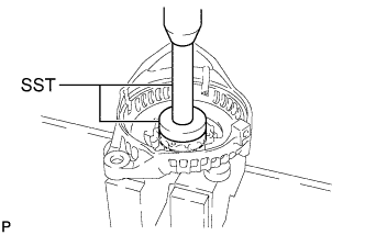
Using SST and a press, install a new generator drive end frame bearing.
- SST
- 09950-60010 ( 09951-00520 )
- 09950-70010 ( 09951-07100 )
-
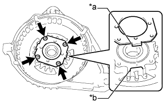
Text in Illustration *a Tab *b Cutout Fit the tabs of the retainer plate into the cutouts of the generator drive end frame to install the retainer plate.
-
Install the 4 screws.
- Torque:
- 2.2 N*m { 22 kgf*cm, 19 in.*lbf }
-
-
INSTALL GENERATOR ROTOR ASSEMBLY
-
Place the generator drive end frame on the generator pulley with clutch.
-
Install the generator rotor assembly to the generator drive end frame.
-
-
INSTALL GENERATOR COIL ASSEMBLY
-
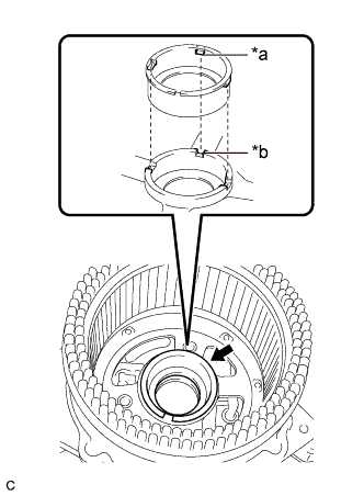
Text in Illustration *a Protrusion *b Groove Install a new bearing cover packing.
Note
Align the protrusions of the bearing cover packing with the grooves of the generator coil assembly when installing.
-
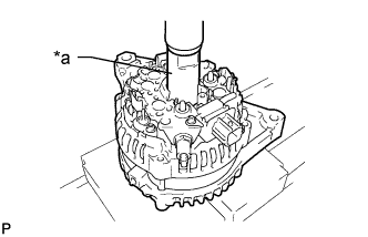
Text in Illustration *a 21 mm Deep Socket Wrench Using a 21 mm deep socket wrench and press, slowly install the generator coil assembly.
-
Install the 4 bolts.
- Torque:
- 5.6 N*m { 57 kgf*cm, 50 in.*lbf }
-
-
INSTALL GENERATOR BRUSH HOLDER ASSEMBLY
-
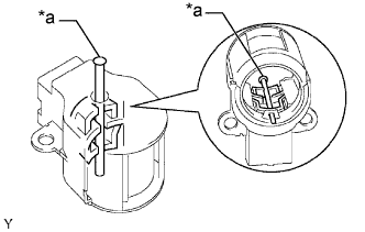
Text in Illustration *a Pin (1.0 mm) While pushing the 2 brushes into the generator brush holder assembly, insert a 1.0 mm (0.0394 in.) pin into the generator brush holder assembly hole.
-
Text in Illustration *a Pin Install the generator brush holder assembly to the generator coil assembly with the 2 screws.
- Torque:
- 1.8 N*m { 18 kgf*cm, 16 in.*lbf }
-
Pull out the pin from the generator brush holder assembly hole.
-
-
INSTALL GENERATOR REAR END COVER
-
Install the generator terminal insulator to the generator coil assembly.
Note
Be sure to install the generator terminal insulator in the correct direction.
-
Install the generator rear end cover to the generator coil assembly with the 3 bolts.
- Torque:
- 4.6 N*m { 47 kgf*cm, 41 in.*lbf }
-
-
INSTALL GENERATOR PULLEY WITH CLUTCH
-
Secure the generator assembly in a vise between aluminum plates.
-
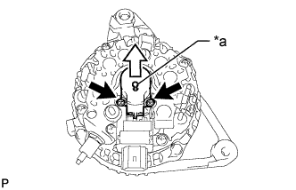
Temporarily install the generator pulley with clutch to the rotor shaft.
-
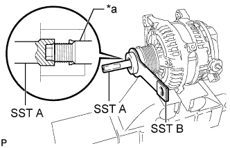
Text in Illustration *a Rotor Shaft Install SST (A) and (B) to the generator pulley with clutch as shown in the illustration.
- SST
- 09820-63021
-
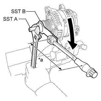
Text in Illustration *a Torque Wrench Fulcrum Length Tighten the generator pulley with clutch by turning SST (B) as shown in the illustration.
- Torque:
- Specified tightening torque
- 111 N*m { 1132 kgf*cm, 82 ft.*lbf }
Note
-
Check that the generator assembly is secured in the vise tightly.
-
Hold SST (A) tightly during the operation.
Tech Tips
-
Calculate the torque wrench reading when changing the fulcrum length of the torque wrench Click here.
-
When using SST (fulcrum length of 100 mm (3.94 in.)) + torque wrench (fulcrum length of 400 mm (15.7 in.)): 89 N*m (908 kgf*cm, 66 ft.*lbf)
-
Remove SST (A) and (B) from the generator pulley with clutch.
-
Check that the generator pulley with clutch rotates smoothly.
-
Remove the generator assembly from the vise.
-