CLEARANCE WARNING ECU REMOVAL
-
PRECAUTION
Note
After turning the ignition switch off, waiting time may be required before disconnecting the cable from the negative (-) battery terminal. Therefore, make sure to read the disconnecting the cable from the negative (-) battery terminal notices before proceeding with work Click here.
-
DISCONNECT CABLE FROM NEGATIVE BATTERY TERMINAL
Note
When disconnecting the cable, some systems need to be initialized after the cable is reconnected Click here.
-
REMOVE FRONT DOOR SCUFF PLATE RH
Tech Tips
Use the same procedure as for the LH side Click here.
-
REMOVE COWL SIDE TRIM SUB-ASSEMBLY RH
Tech Tips
Use the same procedure as for the LH side Click here.
-
DISCONNECT FRONT DOOR OPENING TRIM WEATHERSTRIP RH
-
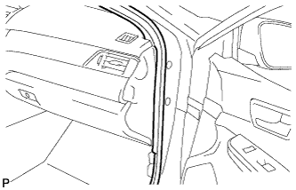
Disconnect the front door opening trim weatherstrip RH.
-
-
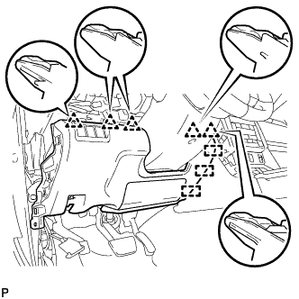
REMOVE INSTRUMENT SIDE PANEL RH
-
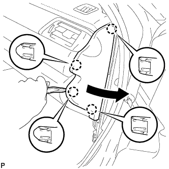
Using a moulding remover, disengage the 4 claws as shown in the illustration.
-
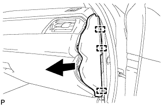
Disengage the 3 guides to remove the instrument side panel RH as shown in the illustration.
-
-
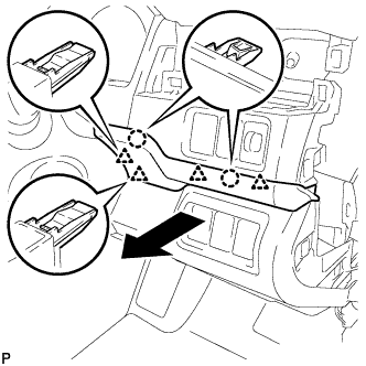
REMOVE FRONT PANEL GARNISH RH
-
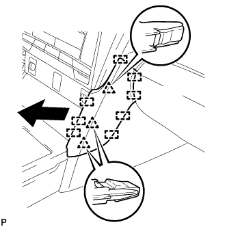
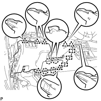
Disengage the 3 clips and 8 guides to remove the front panel garnish RH.
-
-
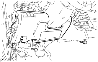
REMOVE NO. 2 INSTRUMENT PANEL UNDER COVER SUB-ASSEMBLY (for LHD)
-
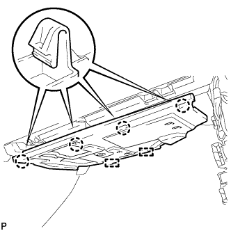
Disengage the 4 claws.
-
Disengage the 2 guides.
-
Disconnect the connector to remove the No. 2 instrument panel under cover sub-assembly.
-
-
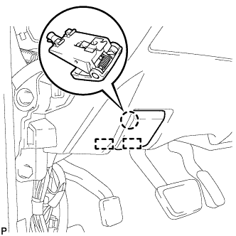
REMOVE LOWER INSTRUMENT PANEL SUB-ASSEMBLY (for LHD)
-
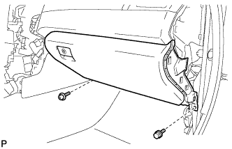
Remove the bolt <B> and screw <D>.
-
Open the lower instrument panel door.
-
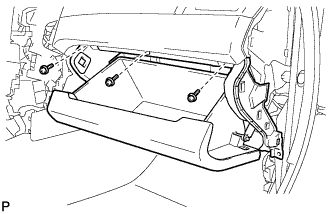
Remove the 3 screws <D>.
-
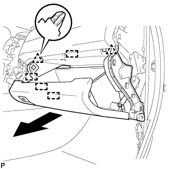
Disengage the 2 clips, 4 guides and remove the lower instrument panel sub-assembly as shown in the illustration.
-
-
REMOVE UPPER INSTRUMENT PANEL FINISH PANEL (for RHD)
-
Disengage the 2 claws and 4 clips to remove the upper instrument panel finish panel as shown in the illustration.
-
w/ Smart Entry and Start System:
-
Disconnect the connector.
-
-
-
DISCONNECT HOOD LOCK CONTROL LEVER SUB-ASSEMBLY (for RHD)
-
Disengage the claw and 2 guides to disconnect the hood lock control lever sub-assembly.
-
-
REMOVE INSTRUMENT PANEL SUB-ASSEMBLY (for RHD)
-
Remove the 2 bolts <B>.
-
w/o Driver Side Knee Airbag:
-
Disengage the 5 clips and 3 guides to remove the instrument panel sub-assembly.
-
-
w/ Driver Side Knee Airbag:
-
Disengage the 4 claws, 7 clips and 3 guides to remove the instrument panel sub-assembly.
-
-
-
REMOVE ECU INTEGRATION BOX RH
-
for LHD:
-
Disconnect each connector.
-
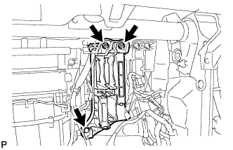
Remove the bolt, 2 nuts and ECU integration box RH.
-
-
for RHD:
-
Disconnect each connector.
-
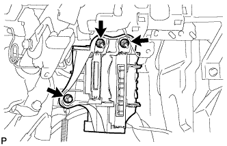
Remove the bolt, 2 nuts and ECU integration box RH.
-
-
-
REMOVE CLEARANCE WARNING ECU ASSEMBLY
-
for LHD:
-
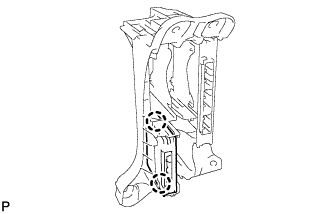
Disengage the 2 claws and remove the clearance warning ECU assembly.
-
-
for RHD:
-
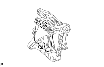
Disengage the 2 claws and remove the clearance warning ECU assembly.
-
-