BLIND SPOT MONITOR SYSTEM, Diagnostic DTC:C1ABD, C1ABE
| DTC Code | DTC Name |
|---|---|
| C1ABD | Short to +B in Buzzer |
| C1ABE | Short to GND or Open in Buzzer |
DESCRIPTION
-
DTC C1ABD is stored when the blind spot monitor sensor LH detects a +B short in RCTA buzzer (blind spot monitor buzzer) circuit.
-
DTC C1ABE is stored when the blind spot monitor sensor LH detects a ground short or open in RCTA buzzer (blind spot monitor buzzer) circuit.
| DTC No. | DTC Detection Condition | Trouble Area |
|---|---|---|
| C1ABD |
When either of the following conditions is met: |
|
| C1ABE |
When either of the following conditions is met: |
|
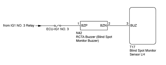
WIRING DIAGRAM
INSPECTION PROCEDURE
Note
-
When checking for DTCs, make sure that the blind spot monitor main switch (warning canceling switch assembly) is on.
-
Inspect the fuses for circuits related to this system before performing the following inspection procedure.
PROCEDURE
-
CHECK DTC
-
Clear the DTCs Click here.
-
Recheck for DTCs and check if the same DTC is output again.
OK No DTCs are output.
NG 
CHECK HARNESS AND CONNECTOR (BATTERY, BLIND SPOT MONITOR SENSOR LH - RCTA BUZZER (BLIND SPOT MONITOR BUZZER)) Click here
OK 
USE SIMULATION METHOD TO CHECK Click here
-
-
CHECK HARNESS AND CONNECTOR (BATTERY, BLIND SPOT MONITOR SENSOR LH - RCTA BUZZER (BLIND SPOT MONITOR BUZZER))
-
Disconnect the T17 blind spot monitor sensor LH connector.
-
Disconnect the N42 RCTA buzzer (blind spot monitor buzzer) connector.
-
Measure the resistance according to the value(s) in the table below.
Standard Resistance Tester Connection Condition Specified Condition N42-2 (BZN) - T17-3 (BUZ) Always Below 1 Ω N42-2 (BZN) - Body ground Always 10 kΩ or higher -
Measure the voltage according to the value(s) in the table below.
Standard Voltage Tester Connection Condition Specified Condition N42-1 (BZP) - Body ground Ignition switch ON 11 to 14 V N42-1 (BZP) - Body ground Ignition switch off Below 1 V
NG 
REPAIR OR REPLACE HARNESS OR CONNECTOR
OK 
-
-
REPLACE RCTA BUZZER (BLIND SPOT MONITOR BUZZER)
-
Replace the RCTA buzzer (blind spot monitor buzzer) with a new or known good one Click here.
NEXT
-
-
CHECK DTC
-
Clear the DTCs Click here.
-
Recheck for DTCs and check if the same DTC is output again.
OK No DTCs are output.
NG
REPLACE BLIND SPOT MONITOR SENSOR LH Click here
OK
END (RCTA BUZZER (BLIND SPOT MONITOR BUZZER) WAS DEFECTIVE)
-