NAVIGATION SYSTEM (for Radio and Display Type), Diagnostic DTC:B15C3
| DTC Code | DTC Name |
|---|---|
| B15C3 | Speaker Output Short |
DESCRIPTION
This DTC is stored when a malfunction occurs in the speakers.
| DTC No. | DTC Detection Condition | Trouble Area |
|---|---|---|
| B15C3 | A short is detected in the speaker output circuit |
|
-
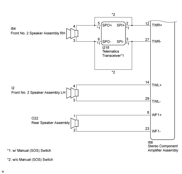
*: w/ Manual (SOS) Switch
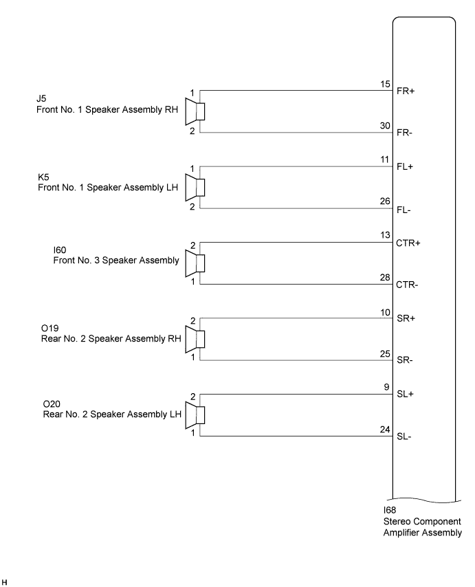
WIRING DIAGRAM
INSPECTION PROCEDURE
Note
Depending on the parts that are replaced during vehicle inspection or maintenance, performing initialization, registration or calibration may be needed. Refer to Precaution for Navigation System. Click here.
PROCEDURE
-
CONFIRM MODEL
-
Choose the model to be inspected.
Result Result Proceed to w/ Manual (SOS) Switch A w/o Manual (SOS) Switch B
B 
CHECK HARNESS AND CONNECTOR (STEREO COMPONENT AMPLIFIER ASSEMBLY OR SPEAKERS - BODY GROUND) Click here
A 
-
-
CHECK HARNESS AND CONNECTOR (STEREO COMPONENT AMPLIFIER ASSEMBLY, TELEMATICS TRANSCEIVER OR SPEAKERS - BODY GROUND)
-
Disconnect the I68 stereo component amplifier assembly connector.
-
Disconnect the I218 telematics transceiver connector.
-
Disconnect the K5 and J5 front No. 1 speaker assembly connectors.
-
Disconnect the I60 front No. 3 speaker assembly connector.
-
Disconnect the O19 and O20 rear No. 2 speaker assembly connectors.
-
Disconnect the O22 rear speaker assembly connector.
-
Disconnect the I2 front No. 2 speaker assembly LH connector.
-
Measure the resistance according to the value(s) in the table below.
Standard Resistance Tester Connection Condition Specified Condition I68-15 (FR+) or J5-1 - Body ground Always 10 kΩ or higher I68-30 (FR-) or J5-2 - Body ground Always 10 kΩ or higher I68-11 (FL+) or K5-1 - Body ground Always 10 kΩ or higher I68-26 (FL-) or K5-2 - Body ground Always 10 kΩ or higher I68-13 (CTR+) or I60-2 - Body ground Always 10 kΩ or higher I68-28 (CTR-) or I60-1 - Body ground Always 10 kΩ or higher I68-10 (SR+) or O19-2 - Body ground Always 10 kΩ or higher I68-25 (SR-) or O19-1 - Body ground Always 10 kΩ or higher I68-9 (SL+) or O20-2 - Body ground Always 10 kΩ or higher I68-24 (SL-) or O20-1 - Body ground Always 10 kΩ or higher I68-8 (WF1+) or O22-1 - Body ground Always 10 kΩ or higher I68-23 (WF1-) or O22-2 - Body ground Always 10 kΩ or higher I68-12 (TWR+) or I218-2 (SPI+) - Body ground Always 10 kΩ or higher I68-27 (TWR-) or I218-3 (SPI-) - Body ground Always 10 kΩ or higher I68-14 (TWL+) or I2-4 - Body ground Always 10 kΩ or higher I68-29 (TWL-) or I2-3 - Body ground Always 10 kΩ or higher
NG 
REPAIR OR REPLACE HARNESS OR CONNECTOR
OK
-
-
CHECK HARNESS AND CONNECTOR (TELEMATICS TRANSCEIVER OR SPEAKERS - BODY GROUND)
-
Disconnect the I218 telematics transceiver connector.
-
Disconnect the I84 front No. 2 speaker assembly RH connector.
-
Measure the resistance according to the value(s) in the table below.
Standard Resistance Tester Connection Condition Specified Condition I218-5 (SPO+) or I84-4 - Body ground Always 10 kΩ or higher I218-6 (SPO-) or I84-3 - Body ground Always 10 kΩ or higher
NG
REPAIR OR REPLACE HARNESS OR CONNECTOR
OK
-
-
INSPECT TELEMATICS TRANSCEIVER
-
Remove the telematics transceiver Click here.
-
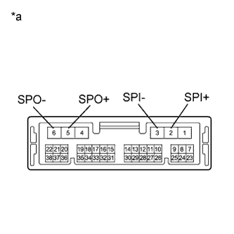
Text in Illustration *a Component without harness connected
(Telematics Transceiver)
Measure the resistance according to the value(s) in the table below.
Standard Resistance Tester Connection Condition Specified Condition 2 (SPI+) - 5 (SPO+) Always Below 1 Ω 3 (SPI-) - 6 (SPO-) Always Below 1 Ω 2 (SPI+) - 3 (SPI-) Always 10 kΩ or higher 5 (SPO+) - 6 (SPO-) Always 10 kΩ or higher 2 (SPI+) or 5 (SPO+) - Body ground Always 10 kΩ or higher 3 (SPI-) or 6 (SPO-) - Body ground Always 10 kΩ or higher Result Result Proceed to NG A OK B
B
INSPECT FRONT NO. 1 SPEAKER ASSEMBLY Click here
A 
REPLACE TELEMATICS TRANSCEIVER Click here
-
-
CHECK HARNESS AND CONNECTOR (STEREO COMPONENT AMPLIFIER ASSEMBLY OR SPEAKERS - BODY GROUND)
-
Disconnect the I68 stereo component amplifier assembly connector.
-
Disconnect the J5 and K5 front No. 1 speaker assembly connectors.
-
Disconnect the I60 front No. 3 speaker assembly connector.
-
Disconnect the O19 and O20 rear No. 2 speaker assembly connectors.
-
Disconnect the O22 rear speaker assembly connector.
-
Disconnect the I84 and I2 front No. 2 speaker assembly connectors.
-
Measure the resistance according to the value(s) in the table below.
Standard Resistance Tester Connection Condition Specified Condition I68-15 (FR+) or J5-1 - Body ground Always 10 kΩ or higher I68-30 (FR-) or J5-2 - Body ground Always 10 kΩ or higher I68-11 (FL+) or K5-1 - Body ground Always 10 kΩ or higher I68-26 (FL-) or K5-2 - Body ground Always 10 kΩ or higher I68-13 (CTR+) or I60-2 - Body ground Always 10 kΩ or higher I68-28 (CTR-) or I60-1 - Body ground Always 10 kΩ or higher I68-10 (SR+) or O19-2 - Body ground Always 10 kΩ or higher I68-25 (SR-) or O19-1 - Body ground Always 10 kΩ or higher I68-9 (SL+) or O20-2 - Body ground Always 10 kΩ or higher I68-24 (SL-) or O20-1 - Body ground Always 10 kΩ or higher I68-8 (WF1+) or O22-1 - Body ground Always 10 kΩ or higher I68-23 (WF1-) or O22-2 - Body ground Always 10 kΩ or higher I68-12 (TWR+) or I84-4 - Body ground Always 10 kΩ or higher I68-27 (TWR-) or I84-3 - Body ground Always 10 kΩ or higher I68-14 (TWL+) or I2-4 - Body ground Always 10 kΩ or higher I68-29 (TWL-) or I2-3 - Body ground Always 10 kΩ or higher
NG
REPAIR OR REPLACE HARNESS OR CONNECTOR
OK
-
-
INSPECT FRONT NO. 1 SPEAKER ASSEMBLY
-
Remove the front No. 1 speaker assembly Click here.
-
Inspect the front No. 1 speaker assembly Click here.
NG
REPLACE FRONT NO. 1 SPEAKER ASSEMBLY Click here
OK
-
-
INSPECT FRONT NO. 3 SPEAKER ASSEMBLY
-
Remove the front No. 3 speaker assembly Click here.
-
Inspect the front No. 3 speaker assembly Click here.
NG
REPLACE FRONT NO. 3 SPEAKER ASSEMBLY Click here
OK
-
-
INSPECT REAR NO. 2 SPEAKER ASSEMBLY
-
Remove the rear No. 2 speaker assembly Click here.
-
Inspect the rear No. 2 speaker assembly Click here.
NG
REPLACE REAR NO. 2 SPEAKER ASSEMBLY Click here
OK
-
-
INSPECT REAR SPEAKER ASSEMBLY
-
Remove the rear speaker assembly Click here.
-
Inspect the rear speaker assembly Click here.
NG
REPLACE REAR SPEAKER ASSEMBLY Click here
OK
-
-
INSPECT FRONT NO. 2 SPEAKER ASSEMBLY
-
Remove the front No. 2 speaker assembly Click here.
-
Inspect the front No. 2 speaker assembly Click here.
NG
REPLACE STEREO COMPONENT AMPLIFIER ASSEMBLY Click here
OK
END
-