AUDIO AND VISUAL SYSTEM (for Radio and Display Type) Reverse Signal Circuit
DESCRIPTION
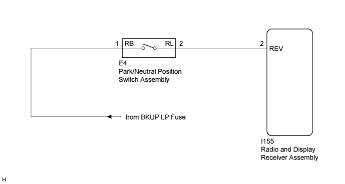
The radio and display receiver assembly receives a reverse signal from the park/neutral position switch assembly.
WIRING DIAGRAM
INSPECTION PROCEDURE
PROCEDURE
-
CHECK BACK-UP LIGHT
-
Move the shift lever to R and check if the back-up lights come on.
OK The back-up lights come on.
NG 
GO TO LIGHTING SYSTEM Click here
OK 
-
-
CHECK HARNESS AND CONNECTOR (REVERSE SIGNAL)
-
Disconnect the I155 radio and display receiver assembly connector.
-
Measure the voltage according to the value(s) in the table below.
Standard Voltage Tester Connection Condition Specified Condition I155-2 (REV) - Body ground Ignition switch ON
Shift lever in R
11 to 14 V I155-2 (REV) - Body ground Ignition switch ON
Shift lever in any position other than R
Below 1 V
NG
REPAIR OR REPLACE HARNESS OR CONNECTOR
OK 
PROCEED TO NEXT SUSPECTED AREA SHOWN IN PROBLEM SYMPTOMS TABLE Click here
-