STEERING COLUMN ASSEMBLY REMOVAL

-
PRECAUTION
-
DISCONNECT CABLE FROM NEGATIVE BATTERY TERMINAL (for Power Tilt and Power Telescopic Steering Column)
-
Disable the auto tilt away function by changing the customize parameter Click here.
Note
Record the current customize parameter setting (whether the auto tilt away function is enabled or disabled) in order to restore the current setting after finishing this operation.
Tech Tips
Performing the above operation disables the auto tilt away function when the ignition switch is turned off.
-
Turn the ignition switch to ON. Operate the tilt and telescopic switch to fully extend and lower the steering column assembly.
-
Turn the ignition switch off and disconnect the cable from the negative (-) battery terminal.
CAUTION:
Wait at least 90 seconds after disconnecting the cable from the negative (-) battery terminal to disable the SRS system.
Note
When disconnecting the cable, some systems need to be initialized after the cable is reconnected Click here.
-
-
TURN FRONT WHEELS TO FACE STRAIGHT AHEAD
-
REMOVE FRONT WHEEL LH
-
REMOVE HORN BUTTON ASSEMBLY
-
for TMMK Made: Click here
-
for TMC, TMMR Made: Click here
-
-
REMOVE STEERING WHEEL ASSEMBLY
-
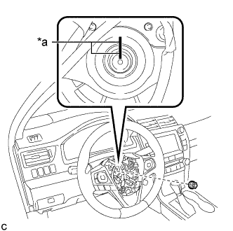
Text in Illustration *a Matchmark Remove the steering wheel assembly set nut.
-
Put matchmarks on the steering wheel assembly and steering main shaft.
-
Disconnect the connectors from the spiral cable sub-assembly.
-
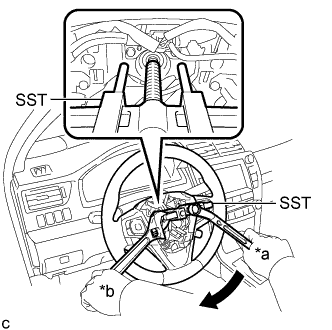
Text in Illustration *a Turn *b Hold Using SST, remove the steering wheel assembly.
- SST
- 09950-50013 ( 09951-05010, 09952-05010, 09953-05020, 09954-05070 )
Note
Apply a small amount of grease to the threads and tip of SST (09953-05020) before use.
-
-
REMOVE FRONT DOOR SCUFF PLATE (w/o Driver Side Knee Airbag)
-

Disengage the 10 claws and remove the front door scuff plate LH.
-
-
REMOVE COWL SIDE TRIM SUB-ASSEMBLY (w/o Driver Side Knee Airbag)
-
Remove the clip.
-
Disengage the 2 clips and remove the cowl side trim sub-assembly LH.
-
-
DISCONNECT FRONT DOOR OPENING TRIM WEATHERSTRIP (w/o Driver Side Knee Airbag)
-

Disconnect the front door opening trim weatherstrip LH.
-
-
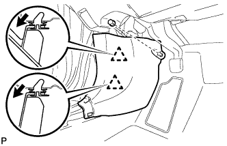
REMOVE INSTRUMENT SIDE PANEL (w/o Driver Side Knee Airbag)
-
Using a moulding remover, disengage the 4 claws as shown in the illustration.
-
Disengage the 3 guides and remove the instrument side panel LH as shown in the illustration.
-
-
DISCONNECT HOOD LOCK CONTROL LEVER SUB-ASSEMBLY (w/o Driver Side Knee Airbag)
-
Disengage the claw and 2 guides to disconnect the hood lock control lever sub-assembly.
-
-
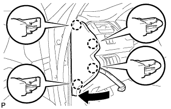
REMOVE INSTRUMENT PANEL SUB-ASSEMBLY (w/o Driver Side Knee Airbag)
-
Remove the 2 bolts <B>.
-
w/o Driver Side Knee Airbag:
-
Disengage the 5 clips and 3 guides to remove the instrument panel sub-assembly.
-
-
w/ Driver Side Knee Airbag:
-
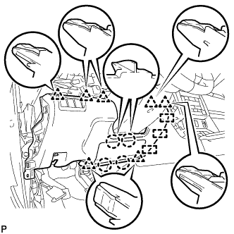
Disengage the 4 claws, 7 clips and 3 guides to remove the instrument panel sub-assembly.
-
-
-
REMOVE LOWER NO. 1 INSTRUMENT PANEL AIRBAG ASSEMBLY (w/ Driver Side Knee Airbag)
-
for TMMK Made: Click here
-
for TMC, TMMR Made: Click here
-
-
REMOVE LOWER STEERING COLUMN COVER (for Manual Tilt and Manual Telescopic Steering Column)
-
Remove the 2 screws.
-
Push the right and left sides of the lower steering column cover, and disengage the 2 claws.
-
Insert a finger into the opening of the tilt lever of the lower steering column cover to disengage the claw and remove the lower steering column cover.
-
-
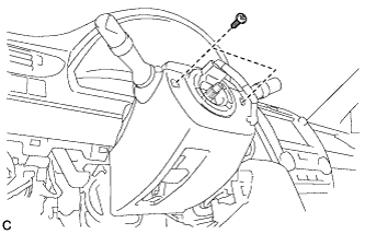
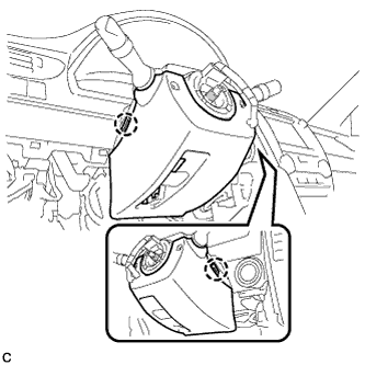
REMOVE LOWER STEERING COLUMN COVER (for Power Tilt and Power Telescopic Steering Column)
-
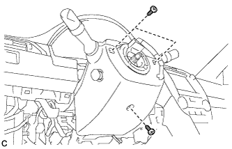
Remove the 3 screws.
-
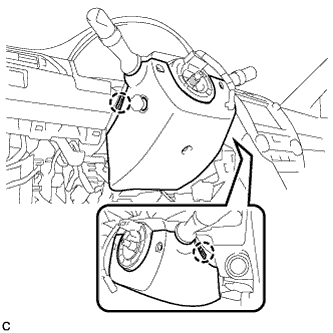
Push the right and left sides of the lower steering column cover, and disengage the 2 claws to remove the lower steering column cover.
Note
Do not damage the tilt and telescopic switch.
-
-
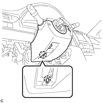
REMOVE UPPER STEERING COLUMN COVER
-
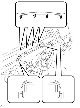
Disengage the 4 clips and 2 guides from the upper steering column cover.
-
Disengage the 2 claws to remove the upper steering column cover.
-
-
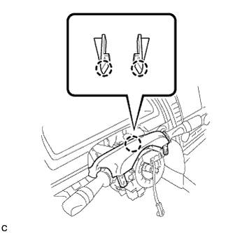
REMOVE TURN SIGNAL SWITCH ASSEMBLY WITH SPIRAL CABLE SUB-ASSEMBLY
-
Disconnect the connectors from the turn signal switch assembly with spiral cable sub-assembly.
-
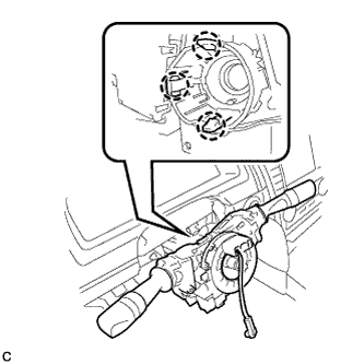
Disengage the 3 claws to remove the turn signal switch assembly with spiral cable sub-assembly from the steering post assembly.
Note
-
Do not replace the spiral cable with the battery connected and the ignition switch ON.
-
Do not rotate the spiral cable with the battery connected and the ignition switch ON.
-
Ensure that the steering wheel is installed and aligned straight when inspecting the steering sensor.
-
-
-
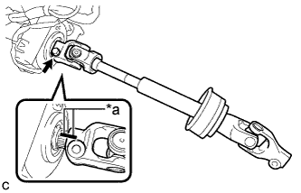
SEPARATE STEERING INTERMEDIATE SHAFT ASSEMBLY
-
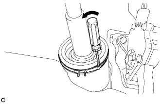
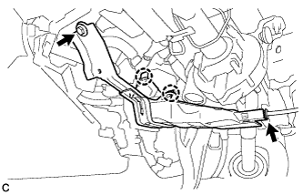
Using a screwdriver, loosen the clamp as shown in the illustration.
-
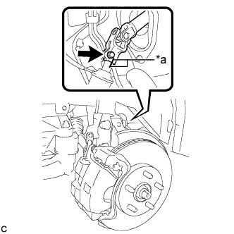
Text in Illustration *a Matchmark Put matchmarks on the steering intermediate shaft assembly and the steering link assembly.
-
Remove the bolt and separate the steering intermediate shaft assembly from the steering link assembly.
-
-
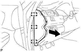
REMOVE NO. 2 AIR DUCT SUB-ASSEMBLY (for LHD)
-
for TMC, TMMR Made:
-
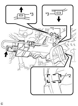
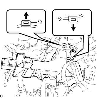
Text in Illustration *1 Guide *2 Clamp *3 Claw Disengage the wire harness clamp from the No. 2 air duct sub-assembly.
-
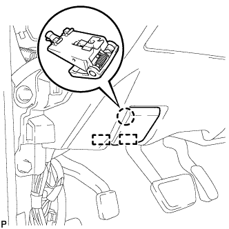
Disconnect the connector from the footwell light.
-
Using a screwdriver, disengage the 2 claws and guide.
Note
Do not lift the claw excessively.
Tech Tips
When disengaging each claw, insert a screwdriver under the end of the claw and lift it gently.
-
Disengage the clamp to remove the No. 2 air duct sub-assembly.
-
-
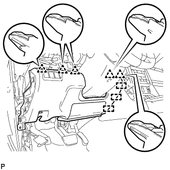
for TMMK Made:
-
Text in Illustration *1 Guide *2 Claw Disengage the 2 claws and guide to remove the No. 2 air duct sub-assembly.
Note
Do not lift the claw excessively.
Tech Tips
When disengaging each claw, insert a screwdriver under the end of the claw and lift it gently.
-
-
-
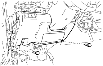
REMOVE NO. 2 AIR DUCT SUB-ASSEMBLY (for RHD)
-
Disconnect the connector from the footwell light.
-
Remove the bolt.
-
Disengage the 2 claws to remove the No. 2 air duct sub-assembly.
-
-
REMOVE STEERING POST ASSEMBLY
-
Disconnect the connectors and disengage the wire harness clamps from the steering post assembly.
-
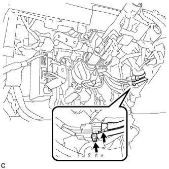
Disconnect the 2 connectors.
-
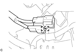
Disengage the clamp.
-
for Manual Tilt and Manual Telescopic Steering Column
-
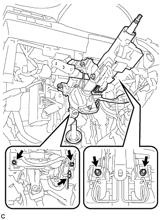
Remove the bolt to separate the ground wire.
-
Remove the 4 nuts and the steering post assembly.
-
-
for Power Tilt and Power Telescopic Steering Column
-
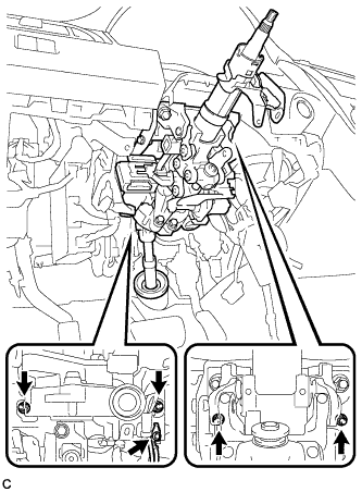
Remove the bolt to separate the ground wire.
-
Remove the 4 nuts and the steering post assembly.
-
-
-
REMOVE STEERING INTERMEDIATE SHAFT ASSEMBLY
-
Text in Illustration *a Matchmark Remove the bolt and slide the steering intermediate shaft assembly.
Note
Do not separate the steering intermediate shaft assembly from the steering column assembly.
-
Put matchmarks on the steering intermediate shaft assembly and the steering post assembly.
-
Remove the steering intermediate shaft assembly from the steering column assembly.
-