PARKING BRAKE PEDAL (for RHD) REMOVAL
-
PRECAUTION
CAUTION:
Be sure to read Precaution thoroughly before servicing Click here.
Note
After turning the ignition switch off, waiting time may be required before disconnecting the cable from the negative (-) battery terminal. Therefore, make sure to read the disconnecting the cable from the negative (-) battery terminal notices before proceeding with work Click here.
-
DISCONNECT CABLE FROM NEGATIVE BATTERY TERMINAL
CAUTION:
Wait at least 90 seconds after disconnecting the cable from the negative (-) battery terminal to disable the SRS system.
Note
When disconnecting the cable, some systems need to be initialized after the cable is reconnected Click here.
-
TURN FRONT WHEELS TO FACE STRAIGHT AHEAD
-
REMOVE FRONT WHEEL RH
-
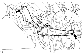
REMOVE SHIFT LEVER SUPPORT
Tech Tips
Use the same procedure as for the LH side Click here.
-
REMOVE NO. 1 INDOOR ELECTRICAL KEY ANTENNA ASSEMBLY
-
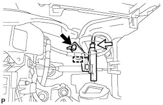
Disengage the clamp.
-
Remove the bolt.
-
Disconnect the connector to remove the No. 1 indoor electrical key antenna assembly.
Note
Be careful when removing the No. 1 indoor electrical key antenna assembly. If the antenna is dropped, replace it with a new one.
-
-
REMOVE FLOOR CARPET BRACKET RH
-
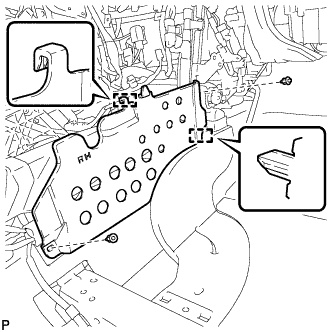
Remove the 2 clips.
-
Disengage the 2 guides to remove the floor carpet bracket RH.
-
-
REMOVE AIRBAG SENSOR ASSEMBLY
-
Check that the ignition switch is off.
-
Check that the cable is disconnected from the negative (-) battery terminal.
CAUTION:
Wait at least 90 seconds after disconnecting the cable from the negative (-) battery terminal to disable the SRS system.
-
Turn back the carpet.
-
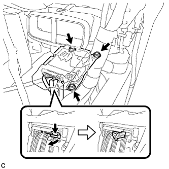
Disconnect the connectors from the airbag sensor assembly as shown in the illustration.
Note
When disconnecting any airbag connector, take care not to damage the airbag wire harness.
-
Remove the 3 bolts and airbag sensor assembly.
-
-
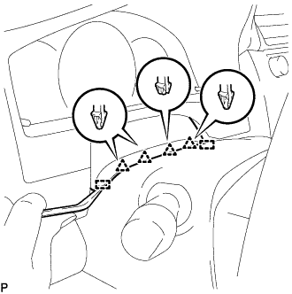
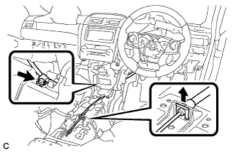
REMOVE UPPER INSTRUMENT PANEL FINISH PANEL
-
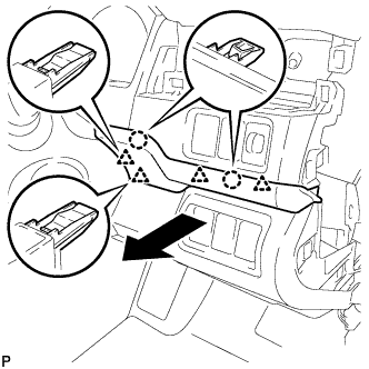
Disengage the 2 claws and 4 clips to remove the upper instrument panel finish panel as shown in the illustration.
-
w/ Smart Entry and Start System:
-
Disconnect the connector.
-
-
-
REMOVE NO. 1 INSTRUMENT PANEL REGISTER ASSEMBLY
Tech Tips
Use the same procedure as for the LH side Click here.
-
REMOVE INSTRUMENT CLUSTER FINISH PANEL ASSEMBLY
-
for Manual Tilt and Manual Telescopic Steering Column:
-
Operate the tilt and telescopic lever to fully extend and lower the steering column assembly.
-
-
Using a moulding remover, disengage the 4 clips and 2 guides.
-
for LHD:
-
Disengage the 3 claws, 7 clips and 4 guides.
-
-
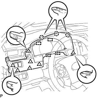
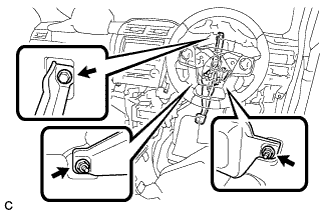
for RHD:
-
Disengage the 4 claws, 5 clips and 4 guides as shown in the illustration.
-
-
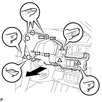
Disconnect each connector.
-
Remove the instrument cluster finish panel assembly as shown in the illustration.
-
-
REMOVE COMBINATION METER ASSEMBLY
Tech Tips
Use the same procedure as for the LH side Click here.
-
REMOVE NO. 2 AIR DUCT SUB-ASSEMBLY
-
Disconnect the connector from the footwell light.
-
Remove the bolt.
-
Disengage the 2 claws to remove the No. 2 air duct sub-assembly.
-
-
SEPARATE STEERING INTERMEDIATE SHAFT ASSEMBLY
Tech Tips
Use the same procedure as for the LH side Click here.
-
REMOVE STEERING INTERMEDIATE SHAFT ASSEMBLY
Tech Tips
Use the same procedure as for the LH side Click here.
-
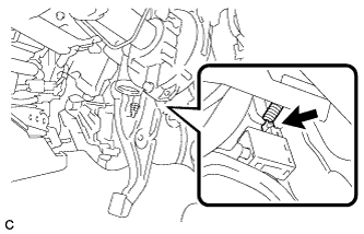
LOOSEN ADJUSTING NUT
-
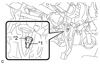
Text in Illustration *1 Lock Nut *2 Adjusting Nut Remove the lock nut and loosen the adjusting nut.
-
-
SEPARATE NO. 4 PARKING BRAKE CABLE ASSEMBLY
-
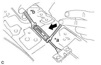
Text in Illustration *a Turn *b Hold Separate the No. 4 parking brake cable assembly from the parking brake control pedal assembly as shown in the illustration.
-
-
REMOVE PARKING BRAKE CONTROL PEDAL ASSEMBLY
-
Remove the clip from the No. 1 parking brake cable assembly.
-
Remove the bolt and separate the No. 1 parking brake cable assembly.
-
Disconnect the parking brake switch connector.
-
Remove the bolt, 2 nuts and parking brake control pedal assembly.
-