VSC OFF SWITCH (for TMC, TMMR Made) REMOVAL
-
REMOVE NO. 1 SWITCH HOLE BASE
-

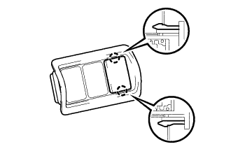
Text in Illustration *1 Protective Tape Apply protective tape to the areas shown in the illustration.
-
Using a moulding remover, disengage the 4 claws and 2 guides as shown in the illustration.
-
Disconnect the connector and remove the No. 1 switch hole base.
-
-
REMOVE VEHICLE STABILITY CONTROL SWITCH (for LHD)
-
Disengage the 2 claws to remove the vehicle stability control switch.
-
-
REMOVE VEHICLE STABILITY CONTROL SWITCH (for RHD)
-
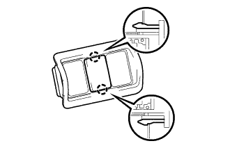
Disengage the 2 claws to remove the vehicle stability control switch.
-