VACUUM WARNING SWITCH INSTALLATION
-
INSTALL CHECK VALVE GROMMET
-
Install a new check valve grommet to the brake booster assembly.
-
-
INSTALL VACUUM WARNING SWITCH ASSEMBLY
-
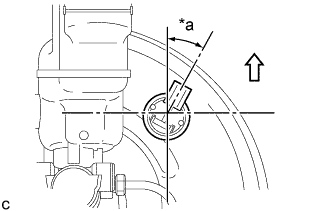
Text in Illustration *a 30° +/- 10° 
Up Install the vacuum warning switch assembly to the brake booster assembly as shown in the illustration.
-
Connect the engine wire connector to the vacuum warning switch assembly.
-
-
INSTALL FRONT OUTER COWL TOP PANEL SUB-ASSEMBLY
-
Install the front outer cowl top panel sub-assembly with the 10 bolts.
- Torque:
- 10 N*m { 102 kgf*cm, 7 ft.*lbf }
-
Engage the 2 clamps to install the wire harness to the front outer cowl top panel sub-assembly.
-
w/ Windshield Deicer System:
-
Connect the connector.
-
Engage the 2 clamps to install the wire harness to the front outer cowl top panel sub-assembly.
-
-
w/ Heated Windshield Defroster System:
-
Connect the 2 connectors.
-
Engage the 4 clamps to install the wire harness to the front outer cowl top panel sub-assembly.
-
-
-
INSTALL WINDSHIELD WIPER MOTOR AND LINK ASSEMBLY