BRAKE BOOSTER (for RHD) INSTALLATION

-
INSTALL CHECK VALVE GROMMET
-
Install a new check valve grommet to the brake booster assembly.
-
-
INSTALL BRAKE VACUUM CHECK VALVE ASSEMBLY
-
Install the brake vacuum check valve assembly to the brake booster assembly.
-
-
INSTALL BRAKE MASTER CYLINDER PUSH ROD CLEVIS
-
Temporarily install the lock nut and brake master cylinder push rod clevis to the brake booster assembly.
-
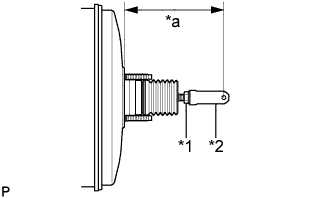
Text in Illustration *1 Lock Nut *2 Brake Master Cylinder Push Rod Clevis *a Push Rod Length Set the push rod length as shown in the illustration.
Push rod length 148.6 to 149.6 mm (5.86 to 5.88 in.) -
Tighten the lock nut.
- Torque:
- 26 N*m { 265 kgf*cm, 19 ft.*lbf }
-
-
INSTALL BRAKE BOOSTER GASKET
-
Install a new brake booster gasket to the brake booster assembly.
-
-
INSTALL BRAKE BOOSTER ASSEMBLY
-
Install the brake booster assembly to the vehicle body with the 4 nuts.
- Torque:
- 13 N*m { 131 kgf*cm, 9 ft.*lbf }
Note
Do not kink or damage the brake lines, air conditioning tube and accessory assembly or suction pipe sub-assembly.
-
-
INSTALL PUSH ROD PIN
-
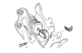
Apply lithium soap base glycol grease to the push rod pin.
Text in Illustration 
Lithium Soap Base Glycol Grease -
Connect the brake master cylinder push rod clevis to the brake pedal support assembly with the push rod pin, and install a new clip as shown in the illustration.
Note
-
Be sure to insert the pin with its clip end facing the outside of the vehicle.
-
Make sure that the brake master cylinder push rod clevis moves sideway.
-
-
-
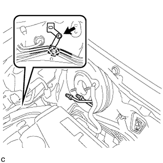
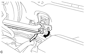
CONNECT UNION TO CHECK VALVE HOSE
-
Connect the union to check valve hose to the brake booster assembly, and slide the clip to secure it.
-
-
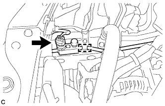
INSTALL VACUUM SWITCHING VALVE ASSEMBLY
-
Install the vacuum switching valve assembly with the bolt.
- Torque:
- 9.0 N*m { 92 kgf*cm, 80 in.*lbf }
-
Connect the 2 vacuum hoses and connector.
-
Connect the union to check valve hose and wire harness clamp.
-
-
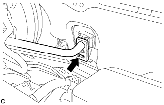
CONNECT BRAKE LINE
-
Install 2 new clamps to the brake lines.
-
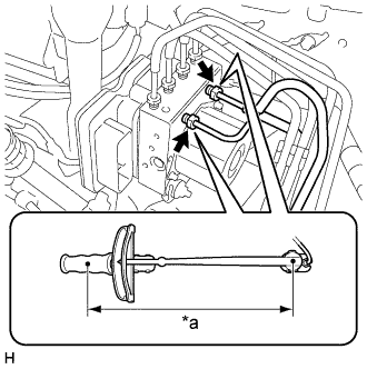
Text in Illustration *a Torque Wrench Fulcrum Length Using a union nut wrench, connect the 2 brake lines to the brake actuator assembly.
- Torque:
- Specified tightening torque
- 20 N*m { 199 kgf*cm, 14 ft.*lbf }
Note
-
Do not kink or damage the brake lines.
-
Do not allow brake lines to twist and interfere with other parts or vehicle body during flexible hose tightening.
-
Do not allow any foreign matter such as dirt or dust to enter the brake lines.
Tech Tips
-
Calculate the torque wrench reading when changing the fulcrum length of the torque wrench Click here.
-
When using a union nut wrench (fulcrum length of 20 mm (0.787 in.)) + torque wrench (fulcrum length of 250 mm (9.84 in.)):
18 N*m (184 kgf*cm, 13 ft.*lbf)
-
-
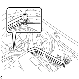
INSTALL NO. 1 BRAKE TUBE CLAMP
-
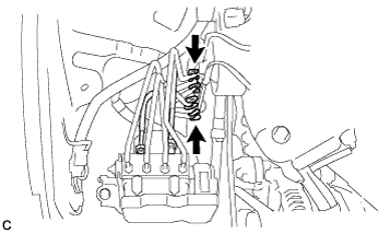
Install a new No. 1 brake tube clamp to the vehicle body.
- Torque:
- 7.8 N*m { 80 kgf*cm, 69 in.*lbf }
-
Engage the brake lines to the clamp.
Note
Do not kink or damage the brake lines.
-
-
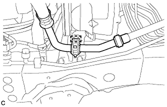
INSTALL SUCTION PIPE SUB-ASSEMBLY
-
Remove the attached vinyl tape from the openings of the disconnected parts.
-
Sufficiently apply compressor oil to a new O-ring, fitting surface of the suction pipe sub-assembly and air conditioning unit.
Compressor oil ND-OIL 8 or equivalent -
Install the O-ring on the suction pipe sub-assembly.
Note
Keep the O-ring and O-ring fitting surfaces free from dirt or any foreign matter.
-
Insert the suction pipe sub-assembly to the air conditioning unit.
Note
-
Insert the pipe joint into the fitting hole securely.
-
Do not deform the piping.
-
Do not damage the plastic clamp.
-
-
Install the clamp with suction pipe sub-assembly and air conditioning tube and accessory assembly to the No. 1 brake tube clamp.
Note
-
Do not deform the air conditioning tube and accessory assembly or suction pipe sub-assembly.
-
Do not damage the plastic clamp.
-
-
Install the clamp to the brake actuator bracket assembly.
Note
-
Do not deform the suction pipe sub-assembly.
-
Do not damage the plastic clamp.
-
-
-
INSTALL AIR CONDITIONING TUBE AND ACCESSORY ASSEMBLY
-
Remove the attached vinyl tape from the openings of the disconnected parts.
-
Sufficiently apply compressor oil to 2 new O-rings, the fitting surface of the air conditioning tube and accessory assembly, cooler condenser assembly and air conditioning unit.
Compressor oil ND-OIL 8 or equivalent -
Install the 2 O-rings on the air conditioning tube and accessory assembly.
Note
Keep the O-ring and O-ring fitting surfaces free from dirt or any foreign matter.
-
Insert the air conditioning tube and accessory assembly to the cooler condenser assembly.
-
Install the bolt.
- Torque:
- 9.8 N*m { 100 kgf*cm, 87 in.*lbf }
-
Insert the air conditioning tube and accessory assembly to the air conditioning unit.
Note
Insert the pipe joint into the fitting hole securely.
-
Turn the hook connector and install the bolt.
- Torque:
- 9.8 N*m { 100 kgf*cm, 87 in.*lbf }
-
Install the clamp to the vehicle body and connect the pressure sensor connector.
Note
-
Do not deform the piping.
-
Do not damage the plastic clamp.
-
-
-
INSTALL RADIATOR SIDE DEFLECTOR RH
-
Engage the guide and 3 claws to install the radiator side deflector RH.
-
-
INSTALL BRAKE MASTER CYLINDER SUB-ASSEMBLY
-
CONNECT CABLE TO NEGATIVE BATTERY TERMINAL
Note
When disconnecting the cable, some systems need to be initialized after the cable is reconnected Click here.
-
CHARGE AIR CONDITIONING SYSTEM WITH REFRIGERANT
-
Perform vacuum purging using a vacuum pump or appropriate equipment.
-
Charge the air conditioning system with refrigerant.
Refrigerant type HFC-134a (R134a) 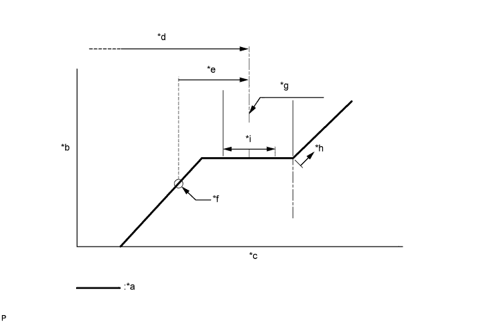
Text in Illustration *a Sub-cool System *b High Pressure *c Refrigerant Amount *d Standard charge amount *e Charge additional 100 g (3.5 oz) *f Point where bubbles disappear *g Mean value in proper range *h Overcharged *i +/-50 g (+/-1.76 oz) - - Standard charge amount 450 to 550 g (15.9 to 19.4 oz) - SST
- 09985-20010 ( 09985-02010, 09985-02050, 09985-02060, 09985-02070, 09985-02080, 09985-02090, 09985-02110, 09985-02130, 09985-02140, 09985-02150 )
Note
-
Do not turn the A/C switch on before charging the air conditioning system with refrigerant. Doing so may cause the compressor to work without refrigerant, resulting in overheating of the compressor.
-
The refrigerant amount should be checked by quantity (weight).
Tech Tips
Ensure that sufficient refrigerant is available to recharge the system when using a refrigerant recovery unit. Refrigerant recovery units are not always able to recover 100% of the refrigerant from an air conditioning system.
-
-
WARM UP ENGINE
-
Keep the A/C switch on for at least 2 minutes to warm up the compressor.
Note
To prevent damage to the compressor, be sure to warm up the compressor when turning the air conditioning on after removing and installing air conditioning system lines (including the compressor).
-
-
INSPECT FOR REFRIGERANT LEAK
-
After recharging the air conditioning system with refrigerant, check for refrigerant leaks using a halogen leak detector.
-
Carry out the test under the following conditions:
-
Turn the engine switch off.
-
Measure the pressure to make sure that there is some refrigerant remaining in the air conditioning system.
Pressure when the compressor is off: approx. 392 to 588 kPa (3.9 to 5.9 kgf/cm2, 57 to 85 psi)
-
Ensure good ventilation (the halogen leak detector may react to volatile gases which are not refrigerant, such as gasoline vapor and exhaust gas).
-
Repeat the inspection 2 or 3 times.
-
-
Remove the front outer cowl top panel sub-assembly Click here for LHD or Click here for RHD).
-
Remove the front bumper assembly Click here.
-
Remove the radiator side deflector RH Click here.
-
Text in Illustration *a Check for leaks *b Halogen Leak Detector Sensor *c Distance between Sensor and Joint to be Checked:
10 mm or less
*d Halogen Leak Detector Sensor Moving Speed:
25 to 50 mm/sec.
How to check for refrigerant leaks in pipe joints:
Note
Gas leaking from a joint can be dissipated by even the slightest breeze. Move the halogen leak detector sensor 360° around each joint instead of keeping it in one spot when checking.
-
Using a halogen leak detector, check for refrigerant leaks at the pipe joints shown in the illustration.
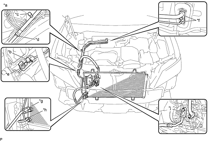
Text in Illustration *a Area to be Checked *b Service Valve (High) *c Service Valve (Low) *d Pipe Joint *e Air Conditioner Pressure Sensor Joint *f Cooler Expansion Valve Joint *g Condenser Joint (Inlet) *h Condenser Joint (Outlet) *i Compressor Joint (Inlet) *j Compressor Joint (Outlet) Tech Tips
-
After the blower motor has stopped, leave the cooling unit for more than 15 minutes.
-
Disconnect the pressure sensor connector and leave it for approximately 20 minutes.
-
When checking for leaks, the presence of oily dirt at a joint can indicate a leak.
Standard There are no refrigerant leaks from the joints. If refrigerant is leaking, disconnect the leaking joint and visually check for the cause, such as the presence of foreign matter.
-
-
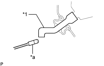
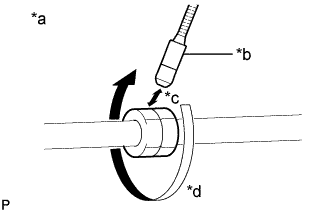
Text in Illustration *1 Drain Cooler Hose *a Halogen Leak Detector Bring the halogen leak detector sensor close to the drain cooler hose with the detector turned off, and then turn the detector on.
Note
Keep water away from the halogen leak detector to prevent malfunction.
Tech Tips
-
After the blower motor has stopped, leave the cooling unit for more than 15 minutes.
-
When bringing the halogen leak detector sensor close to the drain cooler hose, make sure that the halogen leak detector does not react to volatile gases. If it is not possible to avoid interference from volatile gases, the vehicle should be lifted up to allow checking for leaks.
Standard Refrigerant is not leaking from the drain cooler hose. If refrigerant is leaking, check for refrigerant leaks from the No. 1 cooler evaporator sub-assembly.
-
-
Remove the blower motor with fan sub-assembly Click here.
-
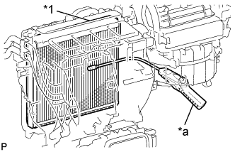
Text in Illustration *1 No. 1 Cooler Evaporator Sub-assembly *a Halogen Leak Detector Insert the halogen leak detector sensor into the air conditioning unit assembly, bring the sensor close to the No. 1 cooler evaporator sub-assembly and check for refrigerant leaks.
Tech Tips
After the blower motor has stopped, leave the cooling unit for more than 15 minutes.
Standard Refrigerant is not leaking from the No. 1 cooler evaporator sub-assembly. If refrigerant is leaking, disconnect the leaking joint and visually check for the cause, such as the presence of foreign matter.
-
Install the blower motor with fan sub-assembly Click here.
-
Install the radiator side deflector RH Click here.
-
Install the front bumper assembly Click here.
-
Install the front outer cowl top panel sub-assembly Click here for LHD or Click here for RHD).
-
-
INSTALL FRONT BUMPER COVER
-
INSPECT AND ADJUST BRAKE PEDAL