FRONT BUMPER (for TMC, TMMR Made) REASSEMBLY
-
INSTALL FRONT BUMPER SIDE RETAINER LH
-
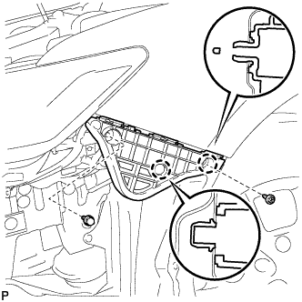
Engage the 2 claws.
-
Install the front bumper side retainer LH with the bolt and screw.
- Torque:
- Bolt
- 5.4 N*m { 55 kgf*cm, 48 in.*lbf }
-
-
INSTALL FRONT BUMPER SIDE RETAINER RH
Tech Tips
Use the same procedure as for the LH side.
-
INSTALL FRONT BUMPER REINFORCEMENT SUB-ASSEMBLY
-
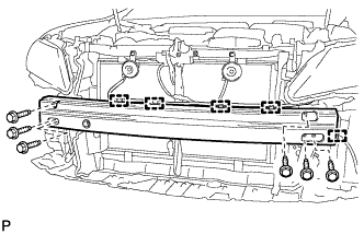
Install the front bumper reinforcement sub-assembly with the 6 bolts.
- Torque:
- 61 N*m { 622 kgf*cm, 45 ft.*lbf }
-
Engage the 5 clamps.
-
-
INSTALL FRONT BUMPER ENERGY ABSORBER
-
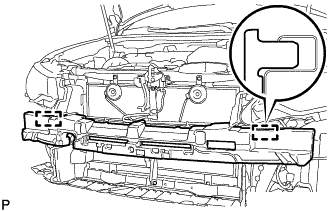
Engage the 2 guides to install the front bumper energy absorber.
-
-
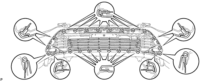
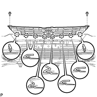
INSTALL LOWER RADIATOR GRILLE SUB-ASSEMBLY
-
Engage the 24 claws.
-
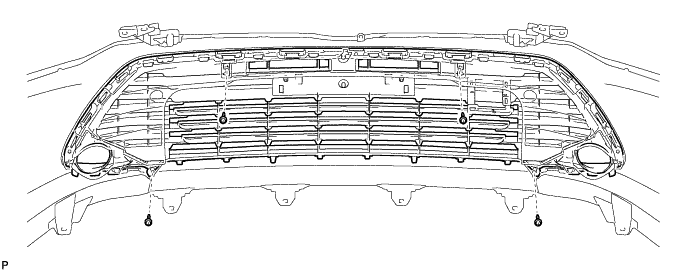
Install the lower radiator grille sub-assembly to the front bumper cover with the 4 screws.
-
-
INSTALL LOWER FRONT BUMPER COVER
-
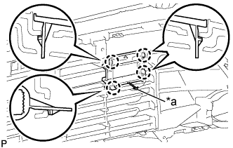
Text in Illustration *a Hook Engage the hook.
-
Engage the 4 claws to install the lower front bumper cover.
-
-
INSTALL FRONT BUMPER HOLE COVER LH
-
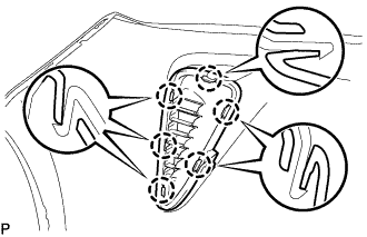
Engage the 6 claws to install the front bumper hole cover LH
-
-
INSTALL FRONT BUMPER HOLE COVER RH
Tech Tips
Use the same procedure as for the LH side.
-
INSTALL RADIATOR GRILLE BRACKET
-
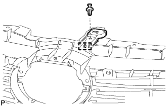
Engage the guide.
-
Install the radiator grille bracket with the clip.
-
-
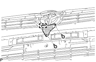
INSTALL RADIATOR GRILLE EMBLEM ASSEMBLY
-
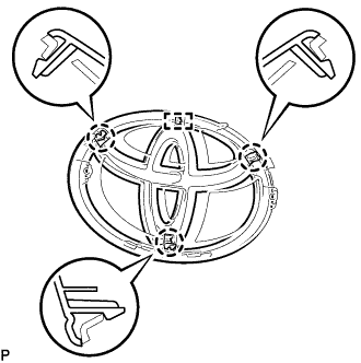
Engage the 3 claws and guide to install the radiator grille emblem assembly to the radiator grille emblem base.
-
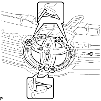
Engage the 4 claws and 2 guides.
-
Install the radiator grille emblem assembly with radiator grille emblem base with the 2 screws.
-
-
INSTALL UPPER RADIATOR GRILLE MOULDING LH
-
Engage the 3 claws.
-
Install the upper radiator grille moulding LH with the screw.
-
-
INSTALL UPPER RADIATOR GRILLE MOULDING RH
Tech Tips
Use the same procedure as for the LH side.
-
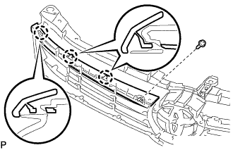
INSTALL RADIATOR GRILLE SUB-ASSEMBLY
-
Engage the 8 claws.
-
Install the radiator grille sub-assembly with the 2 clips.
-
-
INSTALL NO. 2 RADIATOR GRILLE BRACKET
-
Engage the guide.
-
Install the No. 2 radiator grille bracket with the 2 screws.
-
-
INSTALL FRONT FENDER LINER RETAINER
-
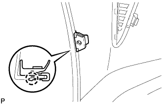
Engage the claw to install the front fender liner retainer.
Tech Tips
Use the same procedure for the RH side and LH side.
-
-
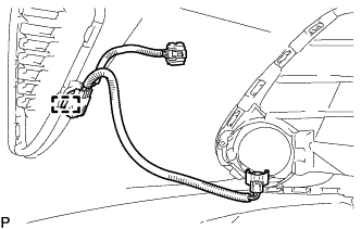
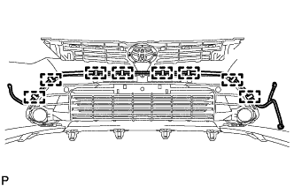
INSTALL NO. 4 ENGINE ROOM WIRE (w/o TOYOTA Parking Assist-sensor System)
-
Engage the clamp to install the No. 4 engine room wire.
Tech Tips
Use the same procedure for the RH side and LH side.
-
-
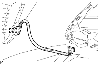
INSTALL NO. 4 ENGINE ROOM WIRE (w/ TOYOTA Parking Assist-sensor System)
-
Engage the clamp to install the No. 4 engine room wire.
Tech Tips
Use the same procedure for the RH side and LH side.
-
-
INSTALL FOG LIGHT ASSEMBLY LH
-
Engage the 2 guides to temporarily install the fog light assembly.
-
Install the fog light assembly with the screw.
- Torque:
- 1.6 N*m { 16 kgf*cm, 14 in.*lbf }
-
Connect the connector.
-
-
INSTALL FOG LIGHT ASSEMBLY RH
Tech Tips
Use the same procedure as for the LH side.
-
INSTALL NO. 1 ULTRASONIC SENSOR RETAINER (w/ TOYOTA Parking Assist-sensor System)
Tech Tips
Use the same procedure for all No. 1 ultrasonic sensor retainers.
-
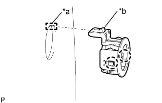
Text in Illustration *a Cutout *b Protrusion Engage the 2 claws to install the No. 1 ultrasonic sensor retainer to the front bumper assembly.
Note
-
Do not damage the front bumper assembly with the protrusion when installing the No. 1 ultrasonic sensor retainer.
-
Securely install the No. 1 ultrasonic sensor retainer so that there are no gaps between the No. 1 ultrasonic sensor retainer and surface of the front bumper assembly.
Tech Tips
-
When installing the retainer, align the cutout and protrusion as shown in the illustration.
-
This illustration is for the LH side. The orientation for the RH side is the opposite of the LH side.
-
-
-
INSTALL NO. 1 ULTRASONIC SENSOR (w/ TOYOTA Parking Assist-sensor System)
Tech Tips
Use the same procedure for all No. 1 ultrasonic sensors.
-
Engage the 2 claws to install the No. 1 ultrasonic sensor to the No. 1 ultrasonic sensor retainer.
Note
Push the No. 1 ultrasonic sensor retainer from the outside of the front bumper assembly when there is a gap between the No. 1 ultrasonic sensor retainer and the front bumper assembly surface. In this case, do not push on the No. 1 ultrasonic sensor.
-
Connect the connector.
-
-
INSTALL HEADLIGHT CLEANER HOSE (w/ Headlight Cleaner System)
-
Engage the 8 clamps to install the headlight cleaner hose.
-
-
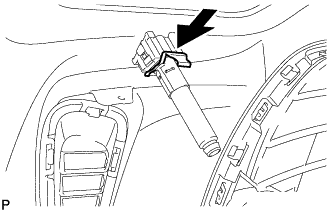
INSTALL HEADLIGHT WASHER ACTUATOR SUB-ASSEMBLY LH (w/ Headlight Cleaner System)
-
Engage the guide as shown in the illustration.
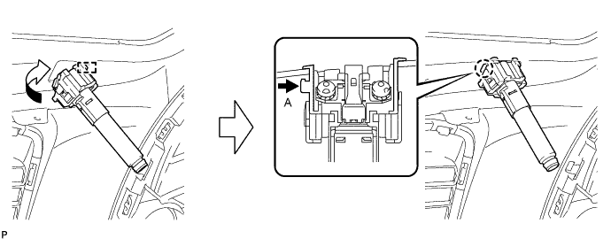
-
While pushing the tab indicated by the arrow (A), engage the claw to install the headlight washer actuator sub-assembly.
-
Push the headlight cleaner actuator clamp as shown in the illustration.
-
Install the headlight cleaner clamp.
-
Connect the headlight cleaner hose.
-
-
INSTALL HEADLIGHT WASHER ACTUATOR SUB-ASSEMBLY RH (w/ Headlight Cleaner System)
Tech Tips
Use the same procedure as for the LH side.
-
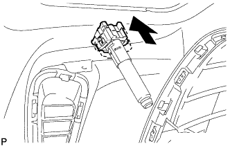
INSTALL HEADLIGHT WASHER NOZZLE SUB-ASSEMBLY LH (w/ Headlight Cleaner System)
-
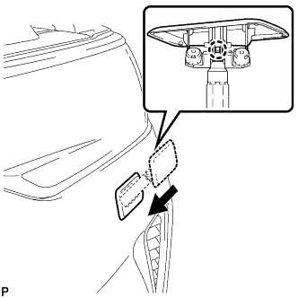
Engage the claw to install the headlight washer nozzle sub-assembly.
-
-
INSTALL HEADLIGHT WASHER NOZZLE SUB-ASSEMBLY RH (w/ Headlight Cleaner System)
Tech Tips
Use the same procedure as for the LH side.