AUTOMATIC HEADLIGHT BEAM LEVEL CONTROL SYSTEM TERMINALS OF ECU
-
CHECK HEADLIGHT LEVELING ECU ASSEMBLY
-
Disconnect the A34 headlight leveling ECU assembly connector.

-
Measure the voltage and resistance according to the value(s) in the table below.
Standard Voltage Terminal No. (Symbol) Wiring Color Terminal Description Condition Specified Condition A34-1 (IG) - Body ground LG - Body ground IG power supply Ignition switch off Below 1 V Ignition switch ON 11 to 14 V Standard Resistance Terminal No. (Symbol) Wiring Color Terminal Description Condition Specified Condition A34-9 (E1) - Body ground W-B - Body ground Ground Always Below 1 Ω If the result is not as specified, there may be a malfunction on the wire harness side.
-
Reconnect the A34 headlight leveling ECU assembly connector.
-
Measure the resistance and voltage according to the value(s) in the table below.
Standard Resistance Terminal No. (Symbol) Wiring Color Terminal Description Condition Specified Condition A34-21 (SGR) - Body ground V - Body ground Rear height control sensor ground Always Below 1 Ω A34-23 (RH-) - Body ground G - Body ground Leveling motor RH ground Always Below 1 Ω A34-24 (LH-) - Body ground B - Body ground Leveling motor LH ground Always Below 1 Ω Standard Voltage Terminal No. (Symbol) Wiring Color Terminal Description Condition Specified Condition A34-3 (B2) - Body ground G - Body ground Low beam headlight signal input Low beam headlights on Below 1.5 V Low beam headlights off 5 V or higher A34-5 (SPDL) - Body ground V - Body ground Initialization signal input Terminals LVL and GND of DLC3 connected Below 1 V Terminals LVL and GND of DLC3 not connected 4.5 to 5.5 V A34-6 (WNG) - Body ground SB - Body ground Warning indicator drive output Warning indicator on Below 1 V Warning indicator off 11 to 14 V A34-10 (RH+) - Body ground R - Body ground Leveling motor RH power supply Ignition switch off Below 1 V Ignition switch ON 11 to 14 V A34-11 (LH+) - Body ground Y - Body ground Leveling motor LH power supply Ignition switch off Below 1 V Ignition switch ON 11 to 14 V A34-12 (SBR) - Body ground B - Body ground Rear height control sensor power supply Ignition switch off Below 1 V Ignition switch ON 4.75 to 5.25 V A34-16 (SPDR) - Body ground P - Body ground*1
L - Body ground*2
Vehicle speed signal input Vehicle driven at approx. 20 km/h (12mph) Pulse generation
(See waveform 1)
A34-17 (RHE) - Body ground W - Body ground Leveling motor RH operation signal input With low beam headlights on, vehicle height not changed Below 1 V With low beam headlights on, vehicle height changed and maintained for more than 3 seconds 1.0 to 14.4 V A34-18 (LHE) - Body ground LG - Body ground Leveling motor LH operation signal input With low beam headlights on, vehicle height not changed Below 1 V With low beam headlights on, vehicle height changed and maintained for more than 3 seconds 1.0 to 14.4 V A34-19 (SHRL) - Body ground R - Body ground Rear height control sensor signal input Ignition switch off Below 1 V Ignition switch ON 0.5 to 4.5 V
-
*1: for TMC, TMMR Made
-
*2: for TMMK Made
If the result is not as specified, the headlight leveling ECU assembly may have a malfunction.
-
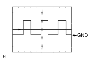
Waveform 1
Item Content Tool setting 2 V/DIV., 2 ms./DIV. Vehicle condition Wheel being rotated
-
-