LIGHTING SYSTEM Low Beam Headlight Circuit
DESCRIPTION
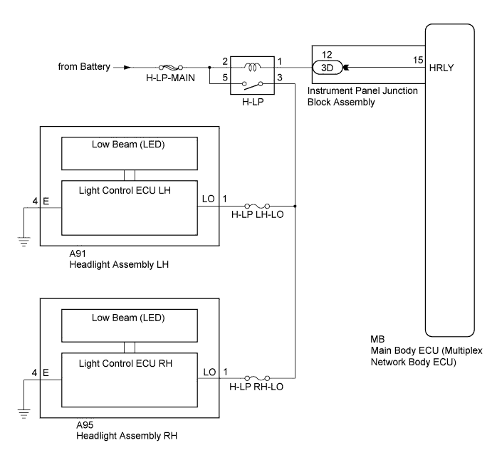
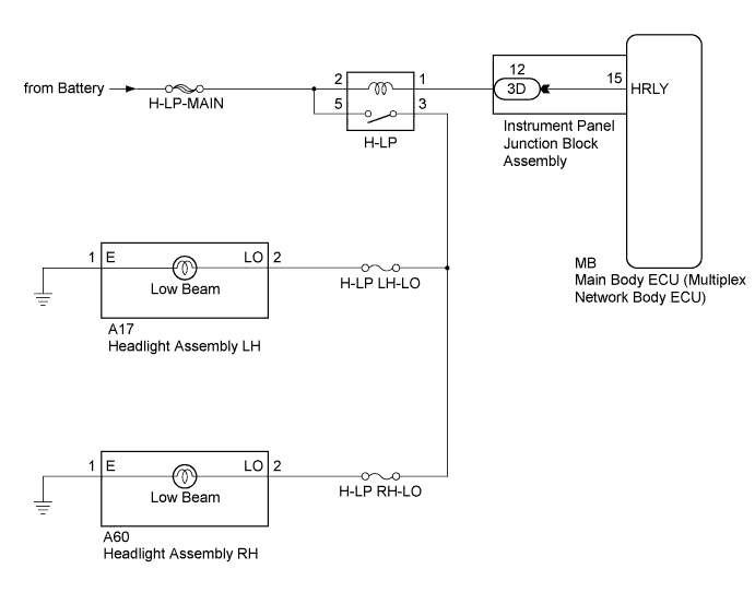
The main body ECU (multiplex network body ECU) controls the low beam headlights via the H-LP relay.
WIRING DIAGRAM
-
for HID Headlight:

-
for LED Headlight:
-
for Halogen Headlight:
INSPECTION PROCEDURE
Note
Inspect the fuses for circuits related to this system before performing the following inspection procedure.
PROCEDURE
-
PERFORM ACTIVE TEST USING INTELLIGENT TESTER
-
Connect the intelligent tester to the DLC3.
-
Turn the ignition switch to ON.
-
Turn the intelligent tester on.
-
Enter the following menus: Body / Main Body / Active Test.
-
Perform the Active Test according to the display on the intelligent tester.
Main Body Tester Display Test Part Control Range Diagnostic Note Headlight Relay Low beam headlights ON/OFF - OK Headlight relay operates. (Low beam headlights illuminate.)
NG 
INSPECT H-LP RELAY Click here
OK 
PROCEED TO NEXT SUSPECTED AREA SHOWN IN PROBLEM SYMPTOMS TABLE Click here
-
-
INSPECT H-LP RELAY
-
Remove the H-LP relay from the engine room relay block and junction block assembly.
-
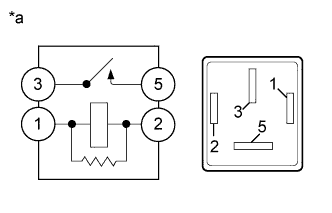
Text in Illustration *a Component without harness connected
(H-LP Relay)
Measure the resistance according to the value(s) in the table below.
Standard Resistance Tester Connection Condition Specified Condition 3 - 5 Voltage not applied between terminals 1 and 2 10 kΩ or higher 3 - 5 Voltage applied between terminals 1 and 2 Below 1 Ω
NG 
REPLACE H-LP RELAY
OK 
-
-
CHECK HARNESS AND CONNECTOR (H-LP MAIN FUSE - H-LP RELAY)
-
Measure the voltage according to the value(s) in the table below.
Standard Voltage Tester Connection Condition Specified Condition Relay Terminal 2 - Body ground Always 11 to 14 V Relay Terminal 5 - Body ground Always 11 to 14 V
NG
REPAIR OR REPLACE HARNESS OR CONNECTOR
OK
-
-
CHECK HARNESS AND CONNECTOR (H-LP RELAY - HEADLIGHT ASSEMBLY LH AND HEADLIGHT ASSEMBLY RH)
-
for HID Headlight:
-
Disconnect the A24 headlight assembly LH connector.
-
Disconnect the A66 headlight assembly RH connector.
-
Measure the resistance according to the value(s) in the table below.
Standard Resistance Tester Connection Condition Specified Condition Relay Terminal 3 - A24-2 (LO) Always Below 1 Ω Relay Terminal 3 - A66-2 (LO) Always Below 1 Ω Relay Terminal 3 - Body ground Always 10 kΩ or higher
-
-
for LED Headlight:
-
Disconnect the A91 headlight assembly LH connector.
-
Disconnect the A95 headlight assembly RH connector.
-
Measure the resistance according to the value(s) in the table below.
Standard Resistance Tester Connection Condition Specified Condition Relay Terminal 3 - A91-1 (LO) Always Below 1 Ω Relay Terminal 3 - A95-1 (LO) Always Below 1 Ω Relay Terminal 3 - Body ground Always 10 kΩ or higher
-
-
for Halogen Headlight:
-
Disconnect the A17 headlight assembly LH connector.
-
Disconnect the A60 headlight assembly RH connector.
-
Measure the resistance according to the value(s) in the table below.
Standard Resistance Tester Connection Condition Specified Condition Relay Terminal 3 - A17-2 (LO) Always Below 1 Ω Relay Terminal 3 - A60-2 (LO) Always Below 1 Ω Relay Terminal 3 - Body ground Always 10 kΩ or higher
-
NG
REPAIR OR REPLACE HARNESS OR CONNECTOR
OK
-
-
CHECK HARNESS AND CONNECTOR (H-LP RELAY - INSTRUMENT PANEL JUNCTION BLOCK ASSEMBLY)
-
Disconnect the 3D instrument panel junction block assembly connector.
-
Measure the resistance according to the value(s) in the table below.
Standard Resistance Tester Connection Condition Specified Condition Relay Terminal 1 - 3D-12 Always Below 1 Ω Relay Terminal 1 - Body ground Always 10 kΩ or higher
NG
REPAIR OR REPLACE HARNESS OR CONNECTOR
OK
-
-
INSPECT INSTRUMENT PANEL JUNCTION BLOCK ASSEMBLY
-
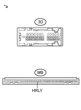
Text in Illustration *a Component without harness connected
(Instrument Panel Junction Block Assembly)
Remove the instrument panel junction block assembly Click here.
-
Remove the main body ECU (multiplex network body ECU) from the instrument panel junction block assembly.
-
Measure the resistance according to the value(s) in the table below.
Standard Resistance Tester Connection Condition Specified Condition 3D-12 - MB-15 (HRLY) Always Below 1 Ω
NG
REPLACE INSTRUMENT PANEL JUNCTION BLOCK ASSEMBLY Click here
OK
REPLACE MAIN BODY ECU (MULTIPLEX NETWORK BODY ECU) Click here
-