LIGHTING SYSTEM Headlight Dimmer Switch Circuit
DESCRIPTION
The main body ECU (multiplex network body ECU) receives the following switch information:
-
Light control switch is in off*1, DRL OFF*2, tail, head or AUTO position
-
Dimmer switch is in high, low or high flash (pass) position
-
Front fog light switch is in on or off position
-
Rear fog light switch is in on or off position
-
*1: for TMC, TMMR Made
-
*2: for TMMK Made
WIRING DIAGRAM
-
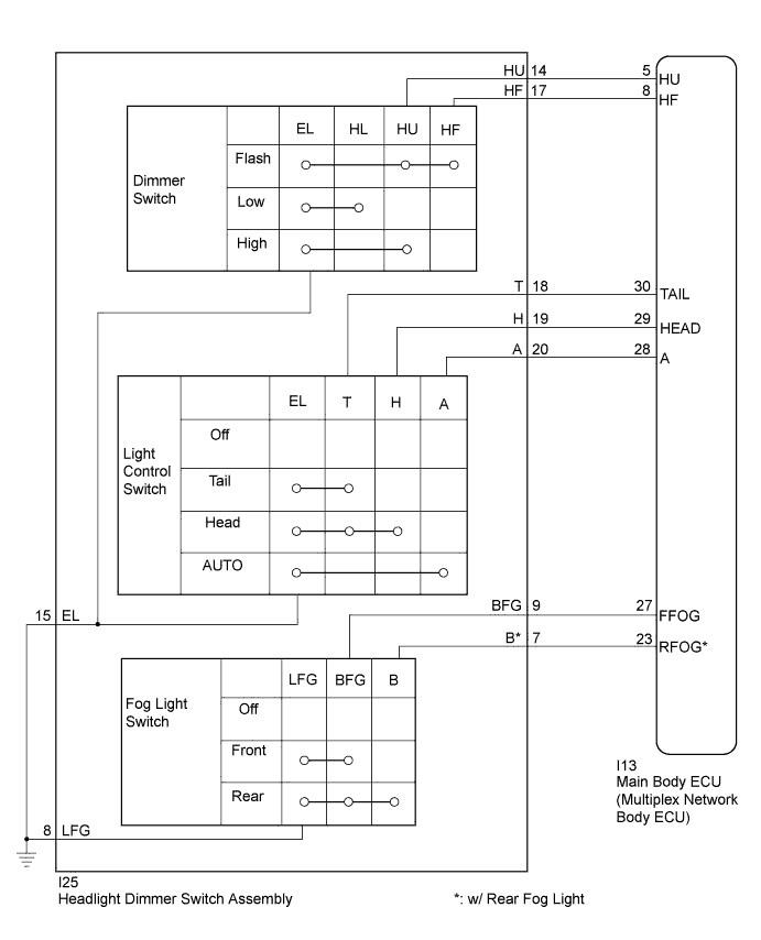
for TMC, TMMR Made LHD:
-
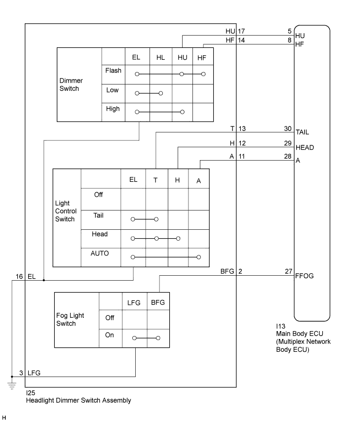
for TMC, TMMR Made RHD:
-
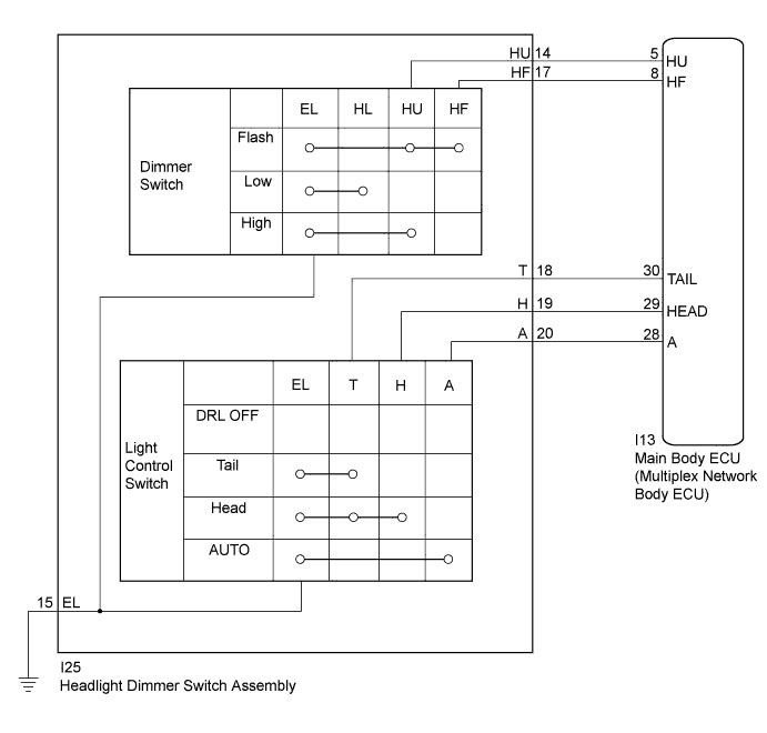
for TMMK Made:
INSPECTION PROCEDURE
PROCEDURE
-
READ VALUE USING INTELLIGENT TESTER
-
Connect the intelligent tester to the DLC3.
-
Turn the ignition switch to ON.
-
Turn the intelligent tester on.
-
Enter the following menus: Body / Main Body / Data List.
-
Read the Data List according to the display on the intelligent tester.
Main Body Tester Display Measurement Item/Range Normal Condition Diagnostic Note Dimmer SW Dimmer switch high position signal/ON or OFF ON: Dimmer switch in high or high flash position
OFF: Dimmer switch in low position
- Passing Light SW Dimmer switch high flash position (pass) signal/ON or OFF ON: Dimmer switch in high flash position
OFF: Dimmer switch not in high flash position
- Rear Fog Light SW*1 Rear fog light switch signal/ON or OFF ON: Rear fog light switch on
OFF: Rear fog light switch off
- Front Fog Light SW*2 Front fog light switch signal/ON or OFF ON: Front fog light switch on
OFF: Front fog light switch off
- Auto Light SW Light control switch AUTO position signal/ON or OFF ON: Light control switch in AUTO position
OFF: Light control switch not in AUTO position
- Head Light SW (Head) Light control switch head position signal/ON or OFF ON: Light control switch in head position
OFF: Light control switch not in head position
- Head Light SW (Tail) Light control switch tail position signal/ON or OFF ON: Light control switch in tail or head position
OFF: Light control switch in neither tail nor head position
-
-
*1: w/ Rear Fog Light
-
*2: w/ Front Fog Light
OK Normal conditions listed above are displayed. -
NG 
INSPECT HEADLIGHT DIMMER SWITCH ASSEMBLY Click here
OK 
PROCEED TO NEXT SUSPECTED AREA SHOWN IN PROBLEM SYMPTOMS TABLE Click here
-
-
INSPECT HEADLIGHT DIMMER SWITCH ASSEMBLY
Tech Tips
Inspect the items that did not change as a result of monitoring the Data List.
-
Remove the headlight dimmer switch assembly (for TMC, TMMR Made: Click here, (for TMMK Made: Click here.
-
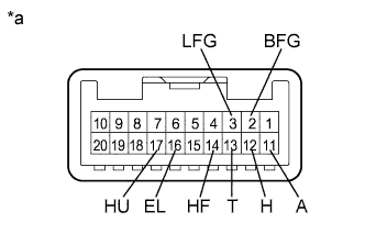
for TMC, TMMR Made LHD:
-
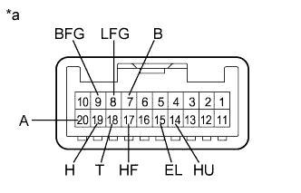
Text in Illustration *a Component without harness connected
(Headlight Dimmer Switch Assembly)
Measure the resistance according to the value(s) in the table below.
Standard Resistance Light Control Switch Tester Connection Condition Specified Condition 15 (EL) - 18 (T) Light control switch off 10 kΩ or higher 18 (T) - 20 (A) Light control switch off 10 kΩ or higher 20 (A) - 19 (H) Light control switch off 10 kΩ or higher 15 (EL) - 18 (T) Light control switch in tail position Below 1 Ω 15 (EL) - 18 (T) Light control switch in head position Below 1 Ω 18 (T) - 19 (H) Light control switch in head position Below 1 Ω 15 (EL) - 20 (A) Light control switch in AUTO position Below 1 Ω Dimmer Switch Tester Connection Condition Specified Condition 14 (HU) - 15 (EL) Dimmer switch in low position 10 kΩ or higher 14 (HU) - 15 (EL) Dimmer switch in high position Below 1 Ω 15 (EL) - 17 (HF) Dimmer switch in high flash position Below 1 Ω Front Fog Light Switch Tester Connection Condition Specified Condition 8 (LFG) - 9 (BFG) Fog light switch off 10 kΩ or higher 8 (LFG) - 9 (BFG) Fog light switch on Below 1 Ω Rear Fog Light Switch* Tester Connection Condition Specified Condition 7 (B) - 8 (LFG) Rear fog light switch off 10 kΩ or higher 7 (B) - 8 (LFG) Rear fog light switch on Below 1 Ω *: w/ Rear Fog Light
-
-
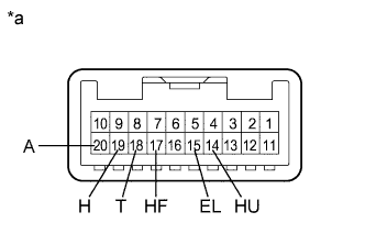
for TMC, TMMR Made RHD:
-
Text in Illustration *a Component without harness connected
(Headlight Dimmer Switch Assembly)
Measure the resistance according to the value(s) in the table below.
Standard Resistance Light Control Switch Tester Connection Condition Specified Condition 16 (EL) - 13 (T) Light control switch off 10 kΩ or higher 13 (T) - 11 (A) Light control switch off 10 kΩ or higher 11 (A) - 12 (H) Light control switch off 10 kΩ or higher 16 (EL) - 13 (T) Light control switch in tail position Below 1 Ω 16 (EL) - 13 (T) Light control switch in head position Below 1 Ω 13 (T) - 12 (H) Light control switch in head position Below 1 Ω 16 (EL) - 11 (A) Light control switch in AUTO position Below 1 Ω Dimmer Switch Tester Connection Condition Specified Condition 17 (HU) - 16 (EL) Dimmer switch in low position 10 kΩ or higher 17 (HU) - 16 (EL) Dimmer switch in high position Below 1 Ω 16 (EL) - 14 (HF) Dimmer switch in high flash position Below 1 Ω Front Fog Light Switch Tester Connection Condition Specified Condition 3 (LFG) - 2 (BFG) Fog light switch off 10 kΩ or higher 3 (LFG) - 2 (BFG) Fog light switch on Below 1 Ω
-
-
Text in Illustration *a Component without harness connected
(Headlight Dimmer Switch Assembly)
for TMMK Made:
-
Measure the resistance according to the value(s) in the table below.
Standard Resistance Light Control Switch Tester Connection Condition Specified Condition 15 (EL) - 18 (T) Light control switch off
(DRL OFF position)
10 kΩ or higher 18 (T) - 20 (A) Light control switch off
(DRL OFF position)
10 kΩ or higher 20 (A) - 19 (H) Light control switch off
(DRL OFF position)
10 kΩ or higher 15 (EL) - 18 (T) Light control switch in tail position Below 1 Ω 15 (EL) - 18 (T) Light control switch in head position Below 1 Ω 18 (T) - 19 (H) Light control switch in head position Below 1 Ω 15 (EL) - 20 (A) Light control switch in AUTO position Below 1 Ω Dimmer Switch Tester Connection Condition Specified Condition 14 (HU) - 15 (EL) Dimmer switch in low position 10 kΩ or higher 14 (HU) - 15 (EL) Dimmer switch in high position Below 1 Ω 15 (EL) - 17 (HF) Dimmer switch in high flash position Below 1 Ω
Result Result Proceed to OK A NG (for TMC, TMMR Made) B NG (for TMMK Made) C -
B 
REPLACE HEADLIGHT DIMMER SWITCH ASSEMBLY Click here
C
REPLACE HEADLIGHT DIMMER SWITCH ASSEMBLY Click here
A 
-
-
CHECK HARNESS AND CONNECTOR (MAIN BODY ECU - HEADLIGHT DIMMER SWITCH ASSEMBLY)
-
Disconnect the I13 main body ECU (multiplex network body ECU) connector.
-
for TMC, TMMR Made LHD:
-
Measure the resistance according to the value(s) in the table below.
Standard Resistance Tester Connection Condition Specified Condition I25-9 (BFG) - I13-27 (FFOG) Always Below 1 Ω I25-7 (B) - I13-23 (RFOG)* Always Below 1 Ω I25-14 (HU) - I13-5 (HU) Always Below 1 Ω I25-17 (HF) - I13-8 (HF) Always Below 1 Ω I25-18 (T) - I13-30 (TAIL) Always Below 1 Ω I25-19 (H) - I13-29 (HEAD) Always Below 1 Ω I25-20 (A) - I13-28 (A) Always Below 1 Ω I25-9 (BFG) - Body ground Always 10 kΩ or higher I25-7 (B)* - Body ground Always 10 kΩ or higher I25-14 (HU) - Body ground Always 10 kΩ or higher I25-17 (HF) - Body ground Always 10 kΩ or higher I25-18 (T) - Body ground Always 10 kΩ or higher I25-19 (H) - Body ground Always 10 kΩ or higher I25-20 (A) - Body ground Always 10 kΩ or higher I25-15 (EL) - Body ground Always Below 1 Ω I25-8 (LFG) - Body ground Always Below 1 Ω
-
*: w/ Rear Fog Light
-
-
-
for TMC, TMMR Made RHD:
-
Measure the resistance according to the value(s) in the table below.
Standard Resistance Tester Connection Condition Specified Condition I25-2 (BFG) - I13-27 (FFOG) Always Below 1 Ω I25-17 (HU) - I13-5 (HU) Always Below 1 Ω I25-14 (HF) - I13-8 (HF) Always Below 1 Ω I25-13 (T) - I13-30 (TAIL) Always Below 1 Ω I25-12 (H) - I13-29 (HEAD) Always Below 1 Ω I25-11 (A) - I13-28 (A) Always Below 1 Ω I25-2 (BFG) - Body ground Always 10 kΩ or higher I25-17 (HU) - Body ground Always 10 kΩ or higher I25-14 (HF) - Body ground Always 10 kΩ or higher I25-13 (T) - Body ground Always 10 kΩ or higher I25-12 (H) - Body ground Always 10 kΩ or higher I25-11 (A) - Body ground Always 10 kΩ or higher I25-16 (EL) - Body ground Always Below 1 Ω I25-3 (LFG) - Body ground Always Below 1 Ω
-
-
for TMMK Made:
-
Measure the resistance according to the value(s) in the table below.
Standard Resistance Tester Connection Condition Specified Condition I25-14 (HU) - I13-5 (HU) Always Below 1 Ω I25-17 (HF) - I13-8 (HF) Always Below 1 Ω I25-18 (T) - I13-30 (TAIL) Always Below 1 Ω I25-19 (H) - I13-29 (HEAD) Always Below 1 Ω I25-20 (A) - I13-28 (A) Always Below 1 Ω I25-14 (HU) - Body ground Always 10 kΩ or higher I25-17 (HF) - Body ground Always 10 kΩ or higher I25-18 (T) - Body ground Always 10 kΩ or higher I25-19 (H) - Body ground Always 10 kΩ or higher I25-20 (A) - Body ground Always 10 kΩ or higher I25-15 (EL) - Body ground Always Below 1 Ω
-
NG
REPAIR OR REPLACE HARNESS OR CONNECTOR
OK
REPLACE MAIN BODY ECU (MULTIPLEX NETWORK BODY ECU) Click here
-